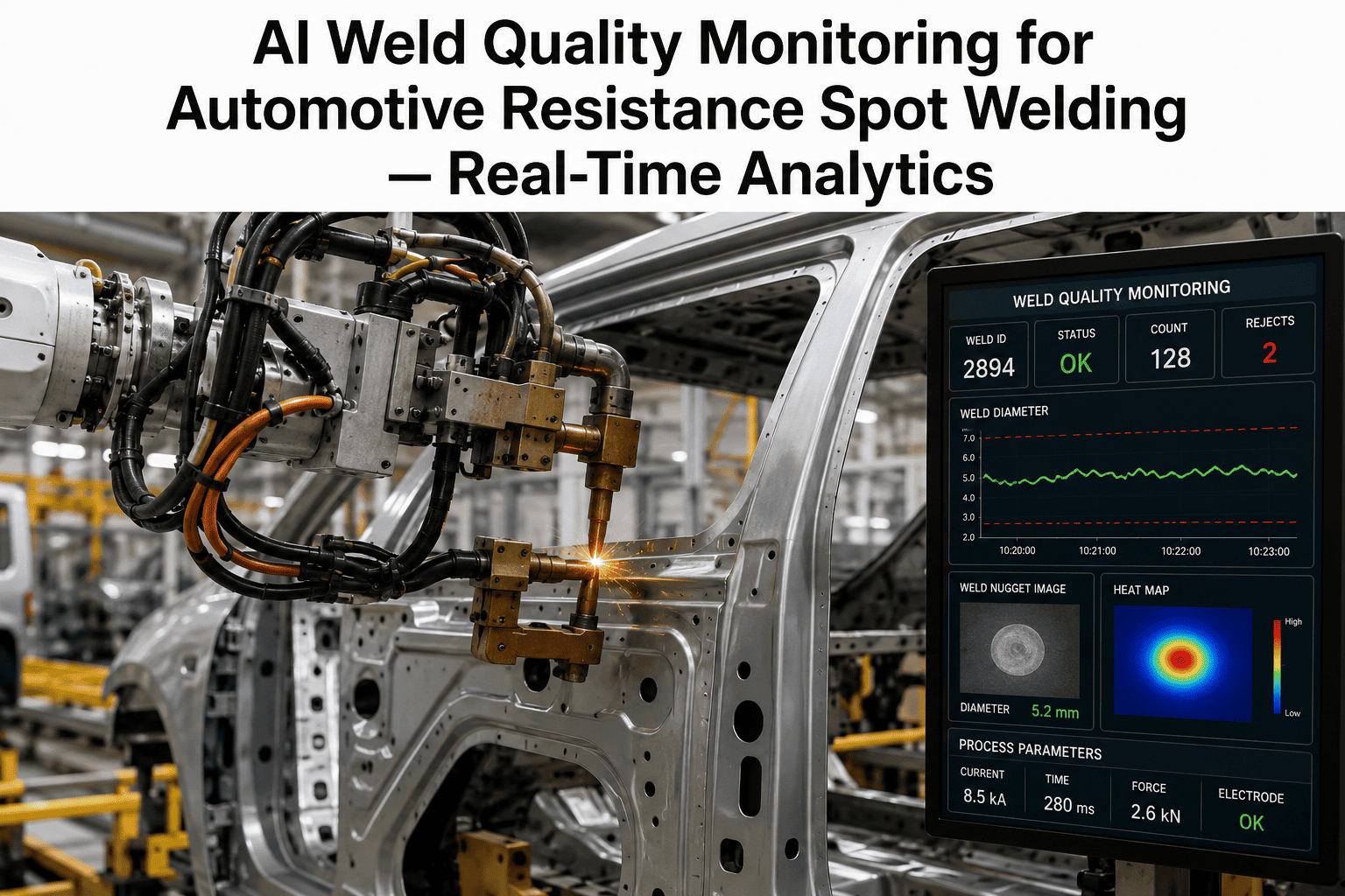
A frame rail can leave the weld cell looking perfect and still carry a hidden pore, a starved toe or a thinned root that only shows up months later in the field. MIG welding on automotive frame lines runs at production speed, so the arc has usually finished its work before anyone knows whether it went well. The good news is that the arc keeps a detailed record of itself, written in voltage, wire feed and travel speed, every fraction of a second. This guide explains how that record is read in real time to catch porosity, spatter and burn-through early, and you can see how the same analysis maps onto your own frame line.
AUTOMOTIVE WELD QUALITY PREDICTION
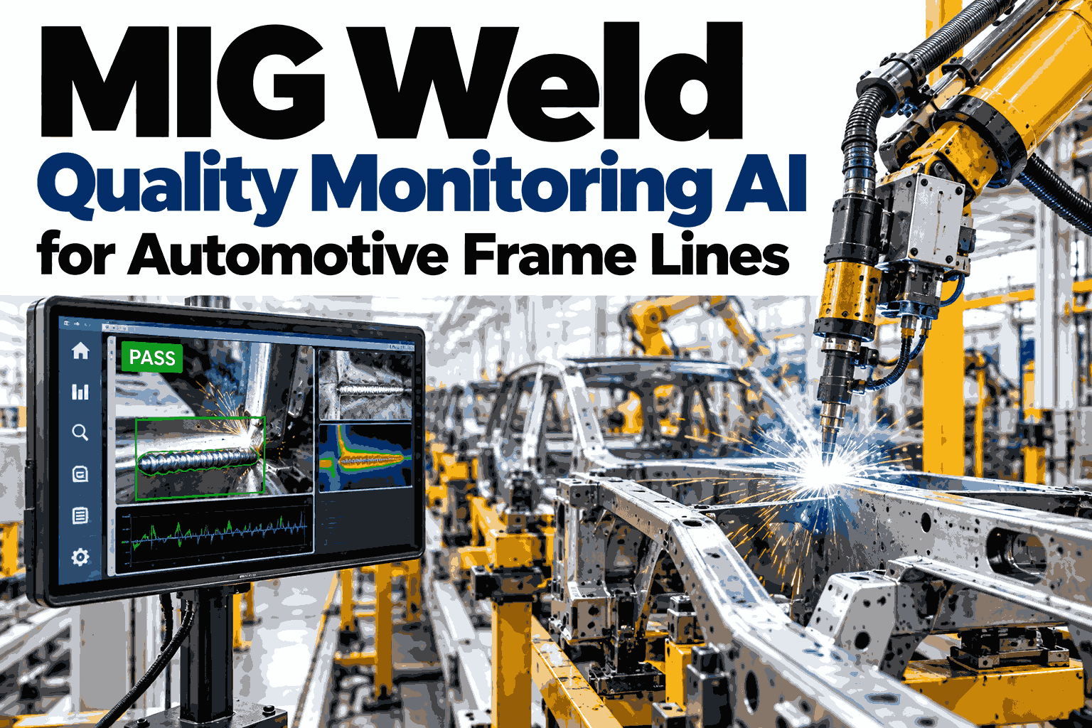
MIG Weld Quality Monitoring AI for Automotive Frame Lines
iFactory reads arc voltage, wire feed and travel speed as the weld is being made, so porosity, spatter and burn-through are flagged while the rail is still in the fixture.
THE INSPECTION GAP
Why Frame Line Welds Fail Quietly
Frame assemblies are long, heavy and welded in many short passes, which means one weak joint can hide among hundreds of good ones.
Arc starts
Defect is created in milliseconds
Joint cools
Surface looks acceptable at line speed
Frame moves on
More rails are welded on the same settings
Defect found
At audit, test bay or in service
The longer the gap between cause and discovery, the more rails share the same fault, so the cost is measured in batches rather than single parts.
Visual checks miss subsurface faults
Porosity trapped below the bead surface and weak fusion at the root do not always show on a quick look at line speed.
Sampling covers only a few parts
Destructive and ultrasonic checks are valuable, yet they can only touch a small share of what the robots produce.
Consumables wear between checks
Contact tips, liners and nozzles degrade gradually, so quality drifts long before any scheduled change.
WHAT THE ARC REVEALS
Three Signals That Describe Every Weld
Each weld leaves a fingerprint in three process signals, and the AI compares that fingerprint with what a good weld on the same joint looks like.
Arc voltage
Reflects arc length and stability. Short-circuit and droplet events show a steady rhythm on a good weld and a ragged one when something is wrong.
Wire feed speed
Sets deposition and current. Slips, hesitations and liner drag appear as dips that disturb the arc within a fraction of a second.
Travel speed
Controls heat input per unit length. A robot slowing through a corner deposits more heat exactly where thin material is least forgiving.
The bars above are illustrative shapes only, showing how a steady signal differs from one that is trending or unstable.
DEFECT SIGNATURES
How Each Defect Shows Up in the Data
Every defect family has a different signature, and that is why one monitoring model can separate them rather than raising a single generic alarm.
| Defect |
Arc voltage pattern |
Wire feed pattern |
Travel speed pattern |
| Porosity |
Sudden arc instability or brief spikes as shielding is disturbed |
Usually steady, which helps rule out feed faults |
Often normal, so cause sits with gas or surface |
| Spatter |
Irregular short-circuit timing and wandering arc length |
Hesitation or surging that upsets droplet transfer |
Rarely the driver, mostly a parameter-balance issue |
| Burn-through |
Falling voltage as the arc sinks into a widening puddle |
Current rising to hold wire feed on thin gauge |
Slowing or dwelling, especially at corners and gaps |
| Lack of fusion |
Steady but low energy relative to the joint |
Low feed for the thickness |
Too fast for the heat delivered |
See which of these signatures your line is already producing
iFactory can review arc data from a representative cell and show how each signal behaves across shifts, consumable ages and part variants.
POROSITY
Tracing Porosity Back to Its Real Cause
Porosity is rarely the fault of the weld itself, since it usually begins upstream with gas coverage, surface condition or hardware wear.
1
Trigger
Clogged nozzle, draft near the cell, oil or mill scale on the joint
2
Shielding breaks
Air reaches the molten pool and gas is trapped as it freezes
3
Arc signature
Voltage trace turns unstable for a short stretch of the seam
4
Prediction
The seam segment is flagged and the likely cause is ranked
Because the flag points to a position along the seam, an inspector can check the suspect section rather than the whole frame.
Gas side clues
Instability that appears at weld start after a nozzle change
Faults that cluster on one side of the cell where drafts enter
Surface side clues
Faults that follow a particular coil or stamping lot
Faults that appear only after a change in cleaning or oiling
SPATTER
Reading Arc Stability Before Spatter Piles Up
Spatter is a symptom of an arc that has lost its balance, which makes it a useful early indicator rather than merely a cleanup problem.
StableDriftingUnstable
Arc stability score moves from stable to unstable as droplet transfer becomes irregular
When the score enters the drifting zone, the system can advise a check of contact tip wear, liner condition and voltage-to-wire-feed balance before spatter becomes visible.
Worn contact tip
Poor current transfer makes the arc wander and short-circuit events lose their rhythm.
Liner drag
Wire hesitates and surges, so droplet size and timing vary along the seam.
Voltage mismatch
An arc too long or too short for the wire feed produces a rougher transfer.
BURN-THROUGH
Heat Input, Gaps and the Thin Gauge Problem
Burn-through happens when heat delivered to the joint exceeds what the material can carry away, and frame lines create that situation in a few predictable ways.
Fast travel
Low heat, risk of poor fusion
Nominal travel
Balanced heat input
Slow at a corner
High heat, risk of burn-through
The bar lengths illustrate relative heat input per unit length at constant current, since slower travel puts more energy into the same stretch of joint.
Common triggers
Robot deceleration through tight corners
Wide fit-up gaps on mating brackets
Thin sections welded with settings tuned for thick ones
Early warning signs
Voltage sagging as the puddle deepens
Current climbing to hold the wire feed
Dwell time longer than the programmed path
REAL-TIME PREDICTION
From Arc Signal to Quality Verdict
The path from raw signal to a decision has to be short, because a verdict that arrives after the frame leaves the fixture cannot prevent anything.
01
Capture
Voltage, current, wire feed and robot position are read continuously from the weld controller and cell.
02
Segment
Each seam is divided into short segments tied to the program step, joint type and part number.
03
Compare
Every segment is compared with a learned reference for a good weld on the same joint and material.
04
Classify
Deviations are labeled as likely porosity, spatter, burn-through or fusion risk, with a confidence level.
05
Act
Suspect frames are routed to inspection and maintenance receives the probable cause with the seam position.
TWO APPROACHES
Post-Weld Inspection Versus In-Process Monitoring
These methods are complementary, but they answer different questions at different moments.
After the weld
Finds defects once the frame is complete
Covers samples rather than every seam
Explains what happened, not why
Rework needs disassembly or repair time
During the weld
Flags risk while the part is still in the fixture
Covers every seam of every frame
Ranks likely causes for maintenance
Targets inspection where it matters
ROLLOUT
A Practical Path to Live Monitoring
A phased start keeps the first cell simple and builds trust in the alerts before the approach spreads across the plant.
Weeks 1-2
Connect and baseline
Link one cell, collect arc data and record what normal looks like for each joint.
Weeks 3-4
Match to outcomes
Tie signal patterns to inspection results so the model learns which deviations matter.
Weeks 5-6
Go live with alerts
Show verdicts to operators and quality teams and tune thresholds with their feedback.
After go-live
Extend to more cells
Reuse the approach on further cells and part families as confidence grows.
CHOOSING A PLATFORM
What to Ask Before You Commit
A short scorecard makes vendor conversations far more concrete than a feature list.
ADoes it work with your existing weld controllers, or does it need new hardware?
BDoes it separate porosity, spatter and burn-through, or give one generic score?
CDoes it point to a position on the seam so inspectors know where to look?
DDoes it learn per joint and part number, rather than applying one universal limit?
EDoes it link findings to maintenance actions such as tips, liners and nozzles?
FREQUENTLY ASKED QUESTIONS
What Quality and Weld Engineers Ask
Does this replace ultrasonic or destructive testing?
No, it works alongside those methods by watching every seam continuously and telling inspectors where to focus. Physical tests still confirm and calibrate what the model flags.
Walk through a live example to see how the two fit together.
Do we need new sensors on our welding cells?
Most modern weld controllers already expose voltage, current and wire feed data, so the first step is usually integration rather than new hardware. Where a signal is missing, the gap can be assessed cell by cell.
Ask our support team about your specific equipment.
How does the system avoid false alarms?
It compares each segment with a reference for the same joint and material, rather than using a single fixed limit for the whole plant. Confidence levels also let teams decide which alerts stop a frame and which only prompt a check.
See the alert logic in a session built around your process.
Can it handle different frame models and materials?
Yes, because references are learned per joint and part number, a change in thickness, grade or fixture is treated as its own case. New variants need a short learning period before alerts become fully reliable.
Contact support to discuss your part mix.
What do maintenance teams receive from the alerts?
They receive the seam position, the likely defect type and a ranked list of probable causes such as tip wear, liner drag or gas coverage. This turns a vague quality complaint into a specific task on a specific cell.
Review a sample alert with our team.
CATCH THE DEFECT AT THE ARC
Stop Finding Weld Problems After the Frame Has Shipped
iFactory turns arc voltage, wire feed and travel speed into real-time quality verdicts for every seam on your automotive frame lines.