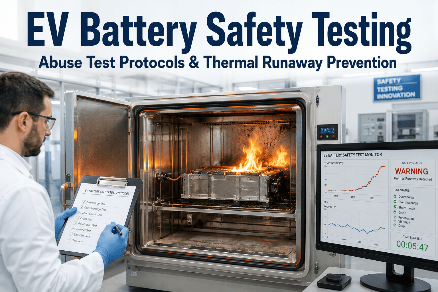
A single thermal runaway event in an EV battery pack can propagate from one failing cell to an entire module in under sixty seconds, and the difference between a design that contains that failure and one that doesn't is measured in seconds of margin engineered months earlier on a test bench. Quality managers overseeing battery safety validation are working against a testing matrix that keeps expanding — nail penetration, crush, overcharge, short circuit, thermal abuse — each protocol producing its own mountain of sensor data that has to be manually reviewed against safety design margins. Most of that review still happens after the test concludes, which means propagation dynamics that unfolded in milliseconds get reconstructed from logged data rather than watched as they happen. AI thermal runaway monitoring changes that — tracking propagation behavior, cell-to-cell thermal spread, and margin validation in real time during the abuse test itself. You can book a demo to see this monitoring layer running against live abuse test data.
Why Battery Abuse Testing Has Become a Quality Bottleneck
Battery safety validation was never simple, but the scope has grown considerably as pack energy densities have climbed and regulatory scrutiny on EV fire incidents has intensified. A single cell chemistry and format now needs to clear a full abuse test matrix — mechanical, electrical, and thermal — before it can move toward pack-level validation, and every test generates thousands of data points across temperature, voltage, pressure, and gas evolution sensors that a quality team has to interpret correctly.
This growth in testing scope has not been matched by a proportional growth in the engineering headcount available to interpret results. Quality teams that could once devote a full day to reviewing a single crush test's sensor traces are now expected to turn results around in hours, because development timelines have compressed at the same time testing requirements have expanded. The result is a structural tension that shows up in almost every battery quality organization today — more tests, more data per test, and less time per test to extract the engineering insight that actually justifies the expense of running it.
The bottleneck isn't running the tests — most quality labs have the equipment and protocols well established. It's the interpretation gap between test completion and a confident engineering judgment about safety margin. A crush test that stops just short of triggering thermal runaway still needs careful analysis to determine how close the design actually came to failure, and that analysis has traditionally required an experienced engineer manually reviewing sensor traces after the fact — a process that doesn't scale well as testing volume grows and development timelines compress.
The Core Abuse Test Matrix Every Battery Design Must Clear
Each abuse test protocol probes a different failure pathway, and a comprehensive safety validation program has to run all of them — not as a checklist exercise, but as a genuine engineering assessment of how close each result came to a safety-critical threshold. No single test can stand in for the others, because a design that performs well under crush loading may still fail an overcharge scenario, and a design robust against external short circuit says nothing about its behavior under nail penetration. Book a demo to see how real-time monitoring applies across each of these protocols specifically.
Running this matrix once is not the same as building a validation program. Cell suppliers change formulations, pack architecture evolves between vehicle programs, and even a seemingly minor change to thermal barrier material or venting geometry can shift propagation resistance in ways that aren't obvious without re-testing. The abuse test matrix isn't a one-time gate a design passes through on its way to production — it's a recurring validation cycle that has to run again every time a material, chemistry, or structural change is introduced, which is exactly why the interpretation speed of each individual test matters so much to overall program throughput.
Inside a Thermal Runaway Event — The Propagation Timeline That Matters
Understanding how a thermal runaway event actually unfolds is essential to interpreting abuse test results correctly. What looks like a single instantaneous failure on a summary report is, at the sensor level, a sequence of distinct stages — and where a design's safety margin sits within that sequence is exactly what real-time monitoring is built to capture. Two tests that both technically "pass" can represent very different levels of actual safety margin depending on how much time elapsed between onset and containment, which is precisely the kind of nuance that gets lost when a report only records a pass or fail outcome.
Navigating the Battery Safety Standards Landscape
Battery safety testing doesn't happen in a regulatory vacuum — every protocol maps to specific standards that vary by market, application, and transport requirements. Quality managers building a validation program need clarity on which standards apply and how AI-assisted monitoring supports compliance documentation for each. A pack destined for both the US and Chinese markets, for example, needs to satisfy UL 2580 and GB 38031 simultaneously — two standards with meaningfully different propagation resistance requirements — which means test documentation has to be structured to demonstrate compliance against each standard's specific criteria rather than a single generic pass/fail record. Book a demo to see how test documentation maps directly to your applicable standards.
| Standard | Scope | Key Test Requirements |
|---|---|---|
| UN 38.3 | Transport safety for lithium batteries | Altitude, thermal cycling, vibration, shock, external short, impact/crush |
| IEC 62660 | Lithium-ion cells for EV propulsion | Performance and reliability testing including thermal and electrical abuse |
| UL 2580 | Batteries for electric vehicle applications | Short circuit, overcharge, crush, thermal exposure at cell and pack level |
| GB 38031 | China EV battery safety mandate | Thermal propagation resistance with 5-minute occupant warning requirement |
| ISO 6469 | Electric road vehicle safety specifications | Functional safety, electrical safety, and post-crash safety requirements |
What AI Monitoring Adds That Post-Test Analysis Cannot
The core limitation of traditional abuse test analysis is timing — insight arrives after the test concludes, when the only options remaining are documentation and design revision for the next iteration. Real-time monitoring shifts that timing, surfacing propagation risk signals while the test is still running and while there's still an opportunity to adjust test parameters or capture additional diagnostic data before the event concludes. This shift matters most during the development phase, when every additional design iteration cycle can cost weeks — and when a monitoring system can tell an engineering team within the same test session that a design change moved the safety margin in the wrong direction, that is weeks of schedule recovered rather than discovered after the fact.
Building a Battery Safety Validation Program — What Quality Managers Need in Place
A mature battery safety validation program is more than a test schedule — it's a documented system connecting test protocols, sensor data, margin criteria, and design change management into a traceable record that satisfies both internal engineering standards and external regulatory audit requirements. Quality managers who have been through a regulatory audit or a post-incident investigation understand exactly why this documentation discipline matters — the question an auditor or investigator asks is rarely "did you run the test," it's "can you show us exactly what the test showed and how that result was interpreted," and a program that can answer that question quickly and completely is in a fundamentally stronger position than one relying on individual engineers' memory of what a given test result meant.