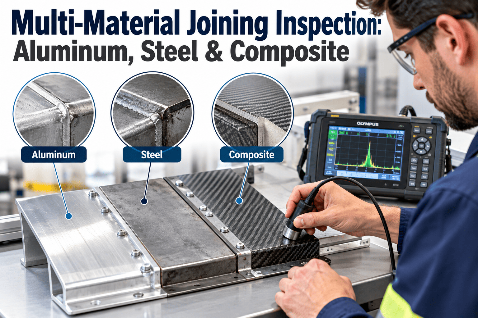
Lightweighting has turned the automotive body into a puzzle of materials that used to be joined by one process and now cannot be. Aluminum will not resistance-spot-weld to steel the way steel welds to itself, and composite panels reject welding altogether, so body shops have shifted to self-piercing rivets, flow-drill screws and structural adhesives to hold dissimilar materials together. Each of those joining methods carries its own failure modes, and none of them are visible from the outside the way a bad weld bead is — which is exactly why verifying joint quality on a mixed-material body needs its own inspection strategy rather than an extension of weld inspection. Engineering teams building that strategy can start by getting iFactory AI's team on a call about their specific material mix.
Verify Every Aluminum, Steel and Composite Joint — Not Just the Welds
iFactory AI inspects self-piercing rivets, flow-drill joints and structural adhesive bonds at line speed, giving lightweight body structures the same 100% coverage that weld inspection already gives steel.
Why Welding Stops Working Once Materials Change
Spot welding depends on both sheets being the same conductive, weldable metal. The moment a body mixes steel with aluminum, or adds a composite panel, that assumption breaks — aluminum's low melting point and oxide layer make it a poor partner for steel in a weld nugget, and composites cannot be welded at all. Automakers turning to aluminum sheet and other lightweight materials found that conventional joining techniques could not ensure the joint integrity a crash-critical structure needs, which pushed the industry toward mechanical and adhesive joining instead.
Resistance spot welding remains the default — same metal, same melting behavior, decades of inspection practice built around it.
Welding is unreliable at best. Self-piercing rivets and rivet-bonding hybrids became the mainstream solution, led by aluminum-intensive programs.
No welding option exists. Structural adhesive, sometimes paired with mechanical fasteners for cure-time clamping, is the standard path.
Three Joining Methods, Three Different Things to Verify
Every joining method produces a different physical structure, so "is this joint good" means something different at each one. Understanding what each method actually forms is the starting point for knowing what an inspection system has to check.
Self-Piercing Rivets (SPR)
A semi-tubular rivet pierces the top sheet and flares within the bottom sheet without fully penetrating it, forming a mechanical interlock. Joint strength depends on rivet height, interlock distance and how symmetrically the rivet leg spreads — all invisible from the finished surface.
Flow-Drill Fastening
A rotating screw generates friction heat, forms its own bushing through the sheets, then threads into that bushing. Quality depends on bushing formation and thread engagement, both of which can fail silently under a visually normal screw head.
Structural Adhesive Bonding
A robotically dispensed adhesive bead cures over the paint-shop cycle, distributing load across the full bond area rather than a point. Bead continuity, width and cure state determine strength, and none of it is visible once panels are mated.
Rivets alone cannot always hit line-rate targets when paired with a bonded-only assembly, and adhesive alone cannot hold panels in place while it cures. The combination — rivets that clamp panels together while structural adhesive cures during the body and paint shop cycle — is now common on aluminum-intensive platforms, which means a single joint location can carry two separate failure modes to inspect at once.
Map Your Joint Mix to the Right Inspection Method
Book a 30-minute session and walk through your rivet, flow-drill and adhesive joint locations with our engineers to see where coverage gaps typically hide.
The Defects That Hide Inside a Good-Looking Joint
A rivet head can look flush and round from above while the joint underneath is compromised. Research into self-piercing rivet failure has catalogued the specific defects that appearance alone cannot catch, and each demands a different inspection approach to surface.
| Joining Method | Hidden Defect | Why It's Invisible Externally |
|---|---|---|
| Self-Piercing Rivet | Undersized interlock, button cracking, rivet offset | Forms beneath the bottom sheet; rivet head can appear correctly seated |
| Self-Piercing Rivet | Angular misalignment of the rivet shank | A few degrees of tilt is imperceptible by eye but cuts joint strength |
| Flow-Drill Fastening | Incomplete bushing, poor thread engagement | Screw head sits flush regardless of bushing quality beneath it |
| Structural Adhesive | Bead discontinuity, voids, under-width application | Fully hidden once the second panel is mated over the bead |
| Structural Adhesive | Incomplete cure at time of load | Cure state cannot be judged visually through the panel skin |
Cracks in a rivet button are frequently too small for manual visual inspection to catch reliably, which is precisely the class of defect that becomes the starting point of an in-service joint failure.
Matching Inspection Technology to Each Joint Type
Because each method forms a different physical structure, no single sensor covers all three. iFactory AI layers vision, ultrasonic and thermal-adjacent techniques across joint types so every joint gets the inspection its physics actually requires.
AI Vision for Surface Geometry
Deep-learning cameras verify rivet head profile, seating, flushness and flow-drill screw position against the qualified geometry at every station, catching offset and misalignment that a human inspector would need a jig and time to measure.
Ultrasonic Verification of Subsurface Form
Narrowband ultrasonic methods couple to the rivet head and read the joint's internal interlock by monitoring transducer impedance against a known-good reference curve, surfacing undersized or cracked joints without cutting a single sample.
Adhesive Bead Monitoring
Inline vision tracks bead presence, width and continuity as it is dispensed, catching gaps and thin sections before the second panel closes over the bond and the defect disappears from view for good.
Process-Curve Pass/Fail Logic
Where a riveting or fastening tool produces a force-displacement curve for every cycle, the system compares that curve against a tolerance band in real time, flagging any joint whose curve drifts before it ever leaves the station.
From Destructive Sampling to 100% Inline Coverage
The traditional way to check a rivet or fastener joint is destructive: cut the joint, polish the cross-section, and inspect it under magnification. That method verifies exactly one joint and destroys it doing so, which is why plants have historically relied on spot sampling and engineer judgment rather than checking every joint on every body.
A Composite Scenario: The Rivet Line That Passed Audits and Still Had a Crack Problem
A body shop running an aluminum-intensive platform was hitting its destructive-sample pass rate every week, with cross-sections showing healthy interlocks on the joints selected for teardown. Field data told a different story — a small but persistent rate of rear-structure squeaks and, in a handful of cases, a warranty claim tracing back to a rivet joint that had failed in service.
When the plant added non-destructive ultrasonic verification across every rivet on the affected panel, the root cause surfaced immediately: a specific die wear condition was producing button cracking on roughly one joint in several hundred, concentrated on one tool and one shift — a pattern too sparse for the existing sample rate to ever catch, and invisible on the rivet head from above. Correcting the die schedule and adding continuous ultrasonic verification on that station closed the gap within weeks.
Building Traceability Into Every Mixed-Material Body
A body with hundreds of rivets, dozens of flow-drill fasteners and multiple adhesive bead runs needs a record that survives the vehicle's life, not just the shift it was built in. iFactory AI ties every joint reading to the body it belongs to, creating the traceable record a mixed-material structure needs.
VIN-Level Joint Records
Every rivet, fastener and adhesive bead inspection ties to the vehicle identifier, so a field question can be answered by pulling the exact joint history rather than a shift-level average.
Station and Tool Correlation
Joint results are logged against the specific riveting head, fastening spindle or adhesive robot that formed them, so a drifting tool shows up as a pattern long before it becomes a field failure.
Supplier and Batch Linkage
Rivet, fastener and adhesive lot data connects to inspection outcomes, isolating whether a quality shift originates on the line or upstream in incoming material.
Audit-Ready Export
Joint inspection records export in the format quality audits and OEM supply reviews expect, replacing a box of cross-section photos with a searchable digital record.
iFactory AI arrives pre-configured on an NVIDIA server that ships racked and ready with software pre-loaded — rack it, connect power and Ethernet, and joint inspection is live. Scope covers cabling, network, PLC and SCADA integration, operator training and 24×7 remote monitoring, so your body shop gets a working multi-material inspection system rather than a parts list to assemble.
Frequently Asked Questions
Can one inspection system cover rivets, flow-drill fasteners and adhesive bonds together?
Yes, though it takes more than one sensing method under one platform rather than a single universal sensor. Vision handles surface geometry and adhesive bead presence, ultrasonic verification reaches the subsurface interlock in rivets, and process-curve monitoring catches fastening anomalies as they happen. iFactory AI layers these methods across the joint types present on a given body so every joining method gets the check its physics actually needs. Reach out and iFactory AI's engineers can review your specific joint mix before recommending a configuration.
Why can't destructive cross-section sampling catch every defect?
Cross-sectioning destroys the joint it inspects, which caps how many joints a plant can afford to check to a small statistical sample per shift. Defects that occur at low, irregular rates — like button cracking tied to a specific worn die — can easily fall between sampled joints for weeks before enough field data accumulates to point back at the cause. Non-destructive methods remove that ceiling because every joint can be checked without being sacrificed, closing the detection gap that sampling leaves open by design.
How does inspection differ between aluminum-to-steel joints and composite-to-metal joints?
Aluminum-to-steel joints are typically mechanical — self-piercing rivets or flow-drill fasteners — so inspection focuses on interlock formation, rivet angle and bushing quality, often verified with vision and ultrasonic methods together. Composite-to-metal joints rely on structural adhesive since composites cannot be riveted or welded the same way, so inspection shifts to bead continuity, width and cure verification during dispensing rather than checking a formed mechanical joint after the fact. A body carrying both joint types needs both inspection approaches running in parallel, not one applied to both.
What happens when a joint fails inspection on the line?
The system flags the specific joint, ties it to the body's VIN and the station that formed it, and routes the result into the plant's quality workflow before the body advances — the same pass/fail discipline that weld inspection already applies, extended to rivets, fasteners and adhesive bonds. Because the record includes the tool and cycle that produced the joint, a repeated flag on the same station points engineers straight at the process condition responsible, whether that is die wear, fastener torque drift or adhesive dispense pressure. Schedule time with iFactory AI to see the flagging workflow on a body shop running today.
Is non-destructive joint inspection as reliable as cutting a sample?
Research into non-destructive rivet inspection — including ultrasonic resonance methods and X-ray computed tomography — has shown the ability to detect the same features a cross-section reveals, including interlock distance, rivet cracks and asymmetry, without destroying the joint. The tradeoff runs the other way in practice: because non-destructive methods can check every joint rather than a handful, they surface low-frequency defect patterns that a limited destructive sample would likely miss entirely, making inline non-destructive coverage the more reliable strategy at fleet scale even though a single cross-section still offers the finest possible detail on one joint.
Give Every Rivet, Fastener and Bond the Coverage Your Welds Already Get
iFactory AI extends 100% inline inspection to the joining methods lightweight bodies actually use, with the vision, ultrasonic and traceability layers each material pairing requires. Book a walkthrough to see it mapped to your body structure.