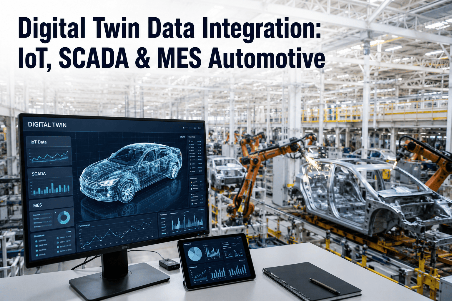
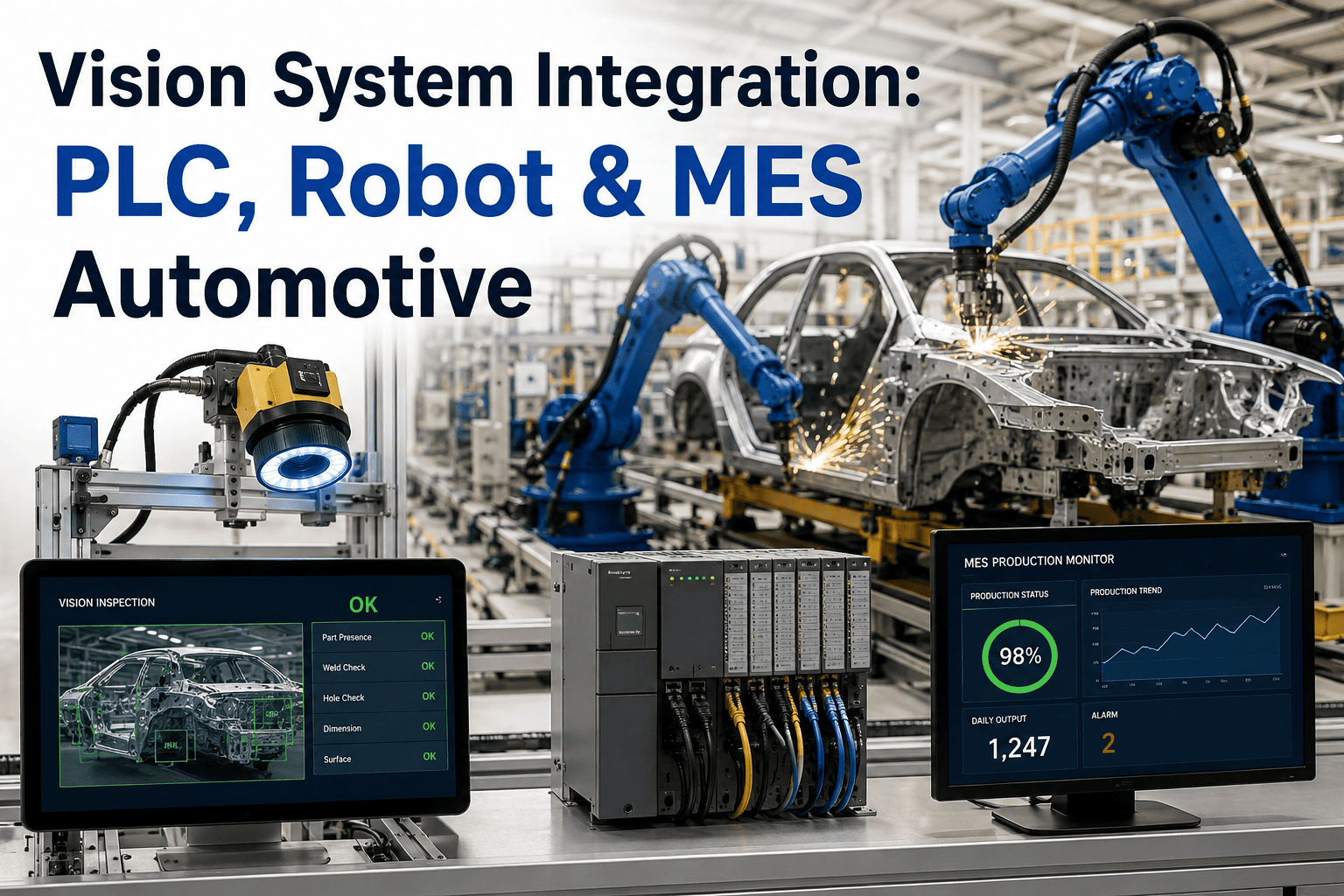
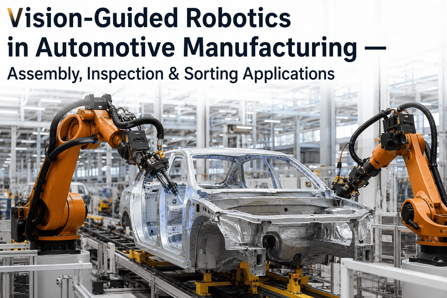
A vision-guided robot that can locate a part with millimeter precision is only half a solution on an automotive line. The other half is whether that robot can tell the PLC it found the part, whether the MES can log which VIN received which weld, and whether a bad read anywhere in that chain stops the line before a defective body-in-white moves downstream. Plant engineers who have lived through a robot cell integration know the failure mode well — the robot vision works perfectly in isolation, then the actual production trial exposes a dozen small gaps between what the robot reports and what the plant's systems expect to receive. Getting vision-guided robotics to actually behave like a connected station, not an island of intelligence bolted onto a cell, is the harder half of the automotive robotics conversation, and it's the part iFactory's integration engineering team spends most of its time solving.
Automotive Robotics · System Integration
Vision-Guided Robotics Integration With PLC and MES Systems in Automotive Plants
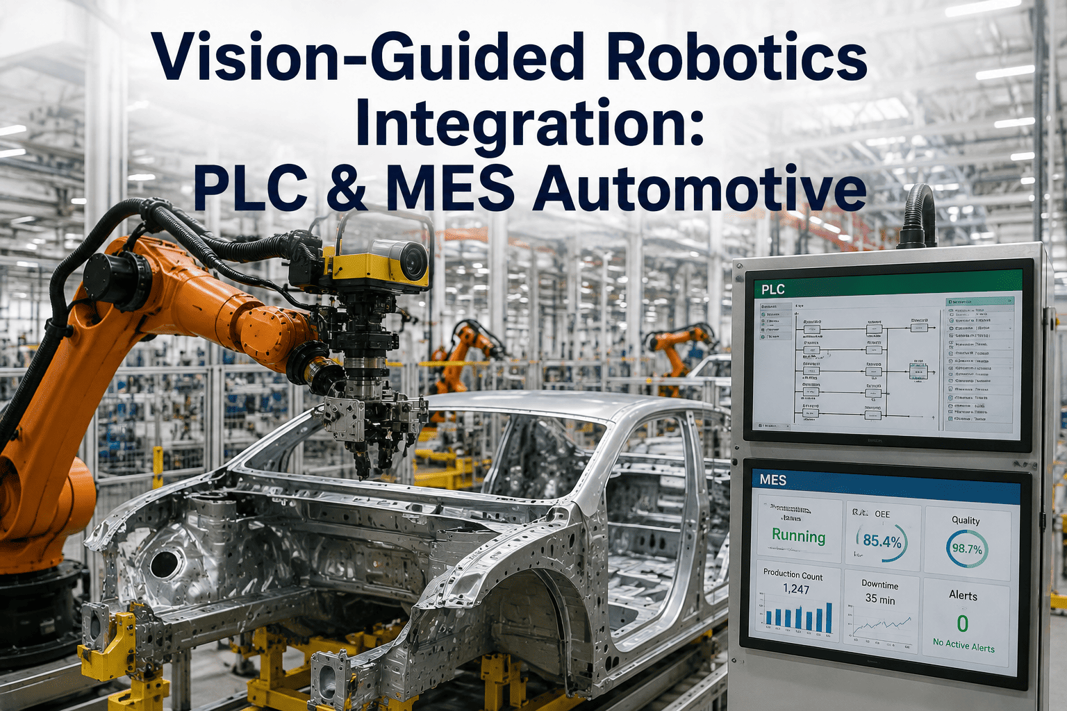
Robot vision only earns its keep on the line when the PLC trusts its trigger signals and the MES trusts its result data. This page walks through the trigger coordination, result reporting, and production data flow that turn a standalone vision-guided robot into a fully connected automotive station.
The Integration Gap
Why Vision Accuracy Alone Doesn't Make a Connected Station
A vision-guided robot arm can be tuned to locate a bracket, a weld nut, or a fastener hole with sub-millimeter repeatability and still fail as a production station if its handshake with the surrounding control architecture is weak. The PLC needs a clean, low-latency trigger to know exactly when the robot is ready to act and exactly when it has finished, because everything else on the line — the conveyor index, the next station's clamp sequence, the safety interlock — is timed against that signal. When the trigger logic is sloppy, the symptom isn't usually a crash; it's a subtle cycle time drift that shows up as unexplained line slowdowns weeks after commissioning.
The MES side of the gap is different but just as consequential. Quality and traceability requirements in automotive assembly mean every weld, fastener, and inspection result needs to be tied to a specific VIN, a specific station, and a specific timestamp — not just logged locally on the robot controller where it's invisible to the plant's quality system. A vision-guided robot that inspects perfectly but reports its results into a proprietary log file the MES never reads has produced data that's functionally worthless for a warranty claim investigation eighteen months later. Closing both gaps — the millisecond-level PLC handshake and the VIN-level MES record — is what separates a robot cell demo from a station that survives a launch audit.
Integration Architecture
The Three-Layer Data Path From Robot Vision to Plant Systems
Every successful vision-guided robotics integration on an automotive line follows a similar layered structure, even when the specific protocols differ by plant. Understanding these three layers helps engineering teams diagnose where a given integration problem actually lives.
Layer 1
Robot Vision and Motion Controller
The vision system locates the part, computes the pose correction, and hands that correction to the robot's motion controller in real time. This layer operates on its own internal cycle, independent of plant networking, and is where the actual guidance intelligence lives.
↕ Discrete I/O or fieldbus handshake
Layer 2
PLC Trigger and Sequence Coordination
The PLC issues the part-present trigger, monitors robot-ready and cycle-complete signals, and sequences the station against the rest of the line — conveyor indexing, clamp actuation, safety zone status. This is the real-time backbone that keeps every station synchronized to a common cycle.
↕ OPC UA, Ethernet/IP, or plant historian tag
Layer 3
MES and Traceability Record
Once the cycle completes, the result — pass, fail, pose correction applied, part serial or VIN — gets written to the MES as a permanent quality record. This layer is not real-time critical in the same way Layer 2 is, but it's the layer regulators, warranty teams, and quality auditors actually query.
Trigger Coordination
Getting the PLC Handshake Right the First Time
Trigger coordination problems are the most common reason a vision-guided robot cell that passed its factory acceptance test still struggles during ramp-up on the actual line. The list below covers the coordination points that need explicit agreement between the robot integrator and the plant's controls engineering team before the cell ever sees a real part.
Part-Present Confirmation
The PLC signal that tells the robot a part has arrived and is stable enough to image needs a defined settling time — imaging a part still swinging on a conveyor hook produces unreliable pose data even from an otherwise accurate vision system.
Robot-Ready Handback
The robot needs a clean way to tell the PLC it has captured a usable image and computed a valid correction, distinct from a fault state — conflating "no valid read yet" with "vision fault" causes false line stops.
Cycle-Complete Timing
The PLC's downstream index timing is set against the robot's cycle-complete signal, so any latency between the robot physically finishing and that signal firing directly eats into available line cycle time.
Fault and Retry Logic
A defined retry count and escalation path for low-confidence vision reads prevents both nuisance line stops on marginal reads and silent pass-through of parts the vision system genuinely couldn't verify.
Safety Zone Interlocks
Vision-guided motion paths that adapt to part position variation still need to respect fixed safety zone boundaries, and the PLC safety logic needs visibility into the robot's adaptive envelope, not just its nominal path.
Network Latency Budget
Whatever protocol carries the trigger and handback — hardwired I/O, Ethernet/IP, Profinet — the round-trip latency needs to be measured and budgeted against the station's cycle time target, not assumed to be negligible.
See the Full Data Path in Action
Watch Vision-Guided Robotics Report Into a Live MES Dashboard
iFactory's integration engineers can walk through a live PLC trigger sequence and MES record write against real automotive station data — bring your controls architecture and we'll map the handshake points specific to your line.
Result Reporting and Traceability
Turning Every Robot Cycle Into a Queryable Quality Record
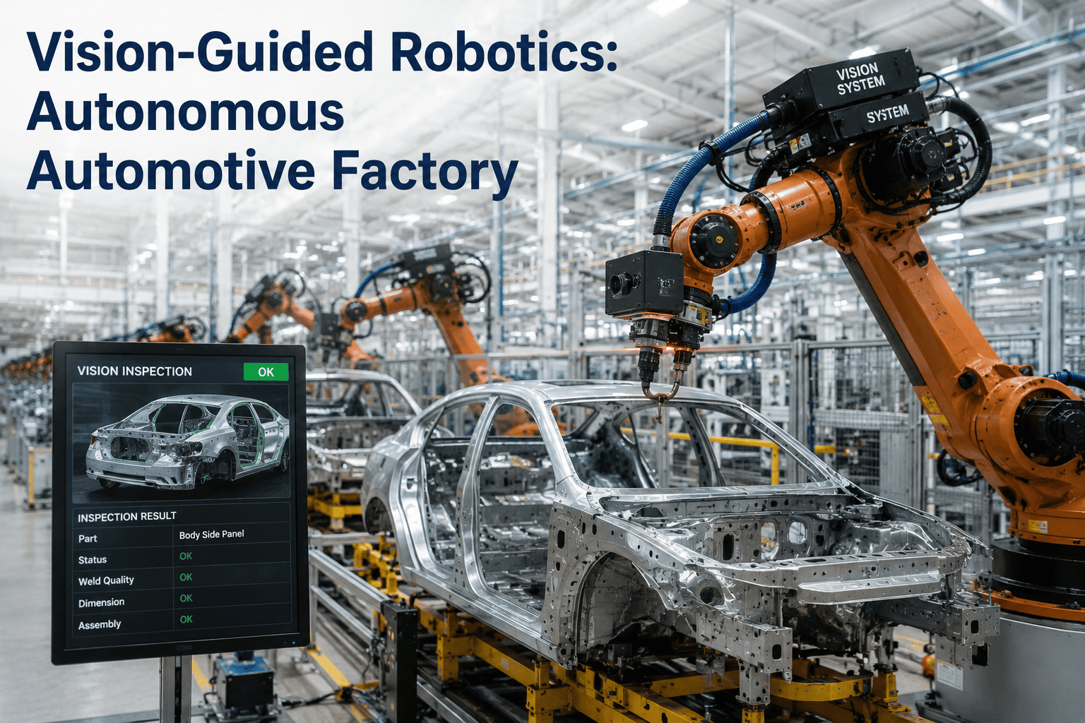
A vision-guided robot generates far more data per cycle than the plant historian typically captures — the raw pose correction, the confidence score, the inspection pass or fail decision, sometimes the image itself. Deciding what subset of that data actually needs to reach the MES, in what format, and tied to what identifier, is a design decision that has to happen before go-live, not discovered during the first warranty investigation that needs it.
VIN-Level Association
Every recorded result needs to trace back to the specific vehicle identification number moving through the station at that cycle, not just a station name and timestamp, so a quality issue can be traced to the exact affected vehicles rather than an entire shift.
Pass/Fail With Supporting Data
A bare pass or fail flag is the minimum useful record; attaching the confidence score and the specific measurement that drove the decision turns a binary log entry into something an engineer can actually use to diagnose a recurring failure pattern.
Pose Correction History
Logging the magnitude of pose correction the robot applied on each cycle, even for passing parts, builds a dataset that can reveal upstream fixturing drift long before it produces an actual defect.
Image Retention Policy
Storing every inspection image indefinitely is rarely practical at automotive volumes, so a defined retention policy — full images for failures, sampled images for passes — balances traceability value against storage cost.
Getting this reporting layer right also determines whether the vision-guided robot's data can feed continuous improvement work later, not just pass/fail compliance. A robot that reports rich pose-correction trends over months of production gives process engineers a lead indicator of fixture wear that no single inspection cycle would ever reveal on its own, and that longer-term visibility is often worth more than the original inspection function that justified the robot's business case. For the same reason, iFactory's engineering team designs the MES data schema for each integration around both the immediate quality need and the improvement analysis a plant will want a year into production.
Protocol Comparison
Choosing the Right Communication Layer for Your Plant Architecture
There is no single correct protocol for connecting vision-guided robotics to PLC and MES layers — the right choice depends on what's already standardized in the plant, the required cycle time, and how much of the existing controls architecture the integration needs to work around.
| Protocol | Typical Layer | Latency Profile | Best Fit |
|---|
| Hardwired Discrete I/O | Robot ↔ PLC | Sub-millisecond | Simple trigger/ready handshakes |
| Ethernet/IP | Robot ↔ PLC | Low, deterministic | Rockwell-standardized plants |
| Profinet | Robot ↔ PLC | Low, deterministic | Siemens-standardized plants |
| OPC UA | PLC ↔ MES | Moderate, non-real-time | Cross-vendor MES connectivity |
| REST/API to MES | Cell ↔ MES | Moderate, batch-friendly | Modern MES platforms, cloud reporting |
A common and effective pattern pairs a hardwired or fieldbus connection for the real-time robot-to-PLC handshake with an OPC UA or REST-based connection for the slower PLC-to-MES traceability write, since the two layers have genuinely different latency and reliability requirements that a single protocol rarely serves equally well.
Plants standardized on a single automation vendor often default to that vendor's native protocol end to end, and there's a reasonable argument for that simplicity — fewer gateway devices, one support relationship, and engineers who already know the tooling. The tradeoff shows up later, when the plant wants to add a second robot cell from a different OEM or connect the same MES to a completely different line that standardized on a different protocol years earlier. Building the PLC-to-MES layer on a vendor-neutral standard like OPC UA from the start avoids having to re-engineer that reporting layer every time the plant's robot vendor mix changes, which is a real and recurring cost in multi-model automotive plants that source robotics from more than one supplier across different vehicle programs.
Deployment Path
From Cell Commissioning to Full Line Integration
iFactory's automotive integration engagements follow a staged path that validates the PLC handshake and MES reporting layers separately before asking the full connected station to run at production rate.
Stage 1
Standalone Vision Validation
The vision-guided robot is validated for pose accuracy and cycle time in isolation, before any PLC or MES connection is introduced, to confirm the core inspection or guidance function meets spec.
Stage 2
PLC Handshake Commissioning
Trigger, ready, and fault signals are wired and tested against the actual plant PLC logic, including deliberate fault injection to confirm retry and escalation behavior works as designed.
Stage 3
MES Record Verification
Result records are verified end to end — a test part run through the station produces exactly the expected VIN-tagged record in the MES, queryable the same way a production quality record would be.
Stage 4
Production-Rate Soak Test
The fully connected station runs at target line rate for an extended soak period, with cycle time, fault rate, and MES record completeness monitored before the cell is handed off as production-ready.
Project Coordination
Who Owns What Across the Robot Vendor, Integrator, and Plant Teams
A vision-guided robotics integration on an automotive line almost never involves a single vendor doing every piece of the work. The robot arm typically comes from one manufacturer, the vision system and its integration software from another supplier, and the PLC and MES connections have to satisfy the plant's own controls standards, which are usually set independently of either vendor. Without a clear ownership map for each layer of the integration, the most common failure pattern isn't a technical defect at all — it's a gap where each party assumes the other one is handling a specific signal, a specific data field, or a specific fault condition, and nobody discovers the gap until commissioning.
The clearest way to avoid that gap is to write the ownership map down before the project starts, not after the first missed handoff. The table below reflects the division of responsibility iFactory typically proposes at project kickoff, adjusted to whatever the plant's existing vendor relationships already look like.
Robot OEM
Owns the robot arm's motion performance, payload and reach specifications, and the base controller's I/O and fieldbus capability — the physical and firmware foundation everything else builds on.
Vision Integrator
Owns the camera selection, lighting design, detection model training, and the specific pose-correction or inspection logic that runs on each cycle — the intelligence layer that makes the robot vision-guided rather than fixed-path.
Plant Controls Engineering
Owns the PLC program, the safety system integration, and the final say on what signals the line's existing control architecture can accept — this team has to approve the trigger and handback design before it goes live.
Plant IT and Quality Systems
Owns the MES platform itself, the data schema for quality records, and the network infrastructure the result data travels across — critical for confirming what the MES can actually ingest before the integrator designs a reporting format around an assumption.
Assigning a single project owner who tracks all four roles against a shared commissioning checklist — even when that owner isn't the technical expert in every layer — is consistently what separates automotive robotics integrations that hit their launch date from ones that discover a missing responsibility during the final week of commissioning. iFactory typically fills that coordination role directly on engagements where the plant doesn't already have a dedicated integration lead assigned.
Common Questions
Frequently Asked Questions
Does adding vision-guided robotics to an existing PLC-controlled line require replacing the PLC?
In the large majority of integrations, the existing PLC stays in place and the robot's vision system is added as another connected device using whatever I/O or fieldbus protocol the PLC already supports, rather than requiring a controller replacement. The main engineering work is defining the new trigger and handback signals within the PLC's existing logic and making sure the added cycle time from the vision step fits within the station's overall time budget. Plants with older PLC hardware that genuinely lacks the I/O capacity or communication protocol needed sometimes do require a controller upgrade, but that's the exception rather than the default starting assumption, and
iFactory's team assesses this during the initial architecture review.
How is VIN-level traceability maintained when the robot only sees a part, not the full vehicle?
The robot's vision system typically doesn't need to identify the VIN itself — that association is made by the PLC or line control system, which already tracks which VIN occupies which position on the line through existing conveyor tracking or RFID tagging, and simply passes that identifier to the robot cell as part of the trigger sequence. The robot's result then gets written back tagged with the VIN the PLC supplied, keeping the vision system focused purely on the inspection or guidance task it's actually good at, while the plant's existing vehicle tracking infrastructure handles the identity association it was already built to do.
What happens to line throughput if the MES connection goes down but the robot is still working?
A well-designed integration decouples the real-time PLC handshake, which governs actual line movement, from the MES reporting connection, which is not typically required to be real-time for the robot to keep cycling. Most architectures buffer result records locally on the robot controller or an edge gateway during an MES outage and replay them once connectivity is restored, so a temporary MES network issue causes a traceability data gap that needs to be backfilled rather than a line stoppage. Whether that buffering is built into a given integration is a design decision worth confirming explicitly during commissioning rather than assuming.
Can one vision-guided robot report to multiple MES modules — quality, maintenance, and production tracking?
Yes, and this is common in mature integrations — a single inspection cycle's data can feed a quality module with the pass/fail and measurement record, a maintenance module with pose-correction trend data that flags fixture wear, and a production tracking module with simple cycle count and uptime data, all from the same underlying result. Structuring the data schema to serve multiple downstream consumers from one write is more efficient than building separate reporting paths for each MES module, and it's a design pattern worth planning for at the outset even if only the quality reporting is required for initial go-live.
How long does a typical PLC and MES integration add to a vision-guided robotics project timeline?
The integration layer typically adds several weeks to a project timeline beyond the standalone vision validation, primarily driven by access to plant controls engineering time and the availability of a test window on the actual line rather than the technical complexity of the handshake itself. Projects that define the trigger signals and MES data schema early, in parallel with the vision system's own development, generally compress this timeline significantly compared to projects that treat integration as an afterthought once the vision system is already working standalone — which is why
booking a scoping call early in a project is worth the time even before hardware is finalized.
Connect the Robot to the Rest of the Plant
Turn Vision-Guided Robotics Into a Fully Traceable Automotive Station
iFactory's integration engineering team designs the PLC handshake and MES data schema alongside the vision system itself, so the connected station is production-ready from the first commissioning run rather than patched together after a failed launch trial. Book a demo to see a live trigger sequence and MES record write, or talk to the team about mapping your specific controls architecture.