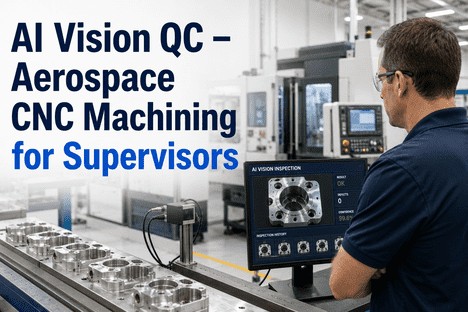
AI Vision QC – Aerospace CNC Machining for Supervisors
By Grace on June 9, 2026
The turbine bracket comes off the 5-axis cell. The operator does a visual check, measures two critical diameters with a hand gauge, and passes it to the next stage. The surface finish on the fillet radius — 8 µin Ra on the drawing — is not checked. Neither is the bore perpendicularity. The part ships. Three weeks later, the customer flags a surface finish escape at incoming inspection. The corrective action request lands on your desk. You pull the production records. There is no in-process inspection data for that feature. There is no SPC chart for surface finish on that operation. There is no way to determine when the condition developed, which tools were in use, or how many other parts in the batch carry the same defect. The NCR closes in 47 days. The same escape happens seven months later. This is the defining quality failure mode in aerospace CNC machining — not dramatic crashes or obvious dimensional failures, but the slow, invisible accumulation of marginal features that manual inspection cannot reliably catch, and that batch-end CMM checks detect too late to prevent repeat escapes. AI vision inspection changes this.
Every Feature That Escapes Inspection on the Floor Becomes an NCR at the Customer. AI Vision Stops It at the Cell.
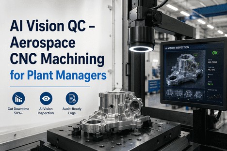
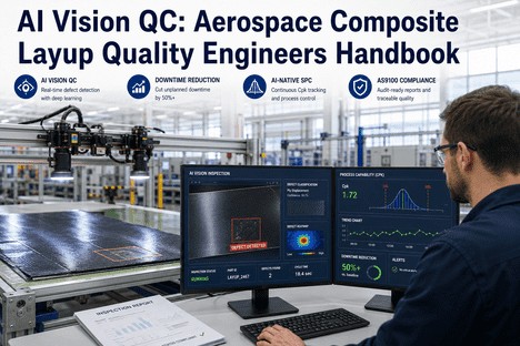
iFactory's AI vision inspection platform catches surface finish deviations, dimensional drift, chatter, and tool-wear escapes at the machine — with self-tuning SPC control limits, real-time supervisor alerts, and AS9100-aligned traceability built into every part record.
Defect reduction achieved by AI-powered inspection systems in precision manufacturing, catching escapes before downstream stages
±0.01 mm
Standard aerospace CNC tolerance — tighter than any hand gauge, and only consistently held with in-process measurement and real-time drift alerts
95%+
Defect detection accuracy demonstrated by AI optical inspection systems in validated CNC machining deployments, versus 60–80% for manual visual inspection
80%
Reduction in defect recurrence rate when AI-detected findings are linked to CNC machining parameter corrections — stopping repeat escapes at source
What Makes Aerospace CNC Machining the Hardest Inspection Environment in Manufacturing
Aerospace CNC machining imposes quality demands that have no equivalent in general manufacturing. Tolerances on structural components run to ±0.01 mm. Engine-critical features like turbine blade root forms require ±0.005 mm or tighter. Surface finish requirements as fine as 8 µin Ra apply to features that contact mating surfaces, seals, or bearings. Every dimension, every surface, and every feature carries a traceability obligation back to the billet, the machine, the tool, and the programme version — because in a flight-critical environment, the question is not just whether the part is in spec, but whether every part in every batch from every machine was in spec on every shift. Manual inspection and periodic CMM checks answer the first question on a sample. AI vision answers the second question on every part.
The Five Defect Categories AI Vision Detects in Aerospace CNC Machining — and Why Manual Inspection Misses Them
Flight-Critical Risk
Surface Finish Deviation
Ra violations on sealing surfaces, bearing bores, and fillet radii are the most common escape from aerospace CNC cells. Tool wear, chip re-cutting, and vibration all degrade surface finish gradually — producing a condition that is borderline on the last tool change and out-of-spec three parts later. Manual visual inspection catches finish anomalies inconsistently. AI vision systems measure Ra proxy values optically on every part, flagging drift before it becomes an escape.
AI detects: Optical surface roughness measurement per feature, correlated with tool life and cutting parameters
Dimensional Risk
Tool Wear Dimensional Drift
Cutting tool wear produces progressive dimensional drift — diameters growing, depths shifting, profiles opening — that develops continuously between tool changes. A part at the start of a tool life interval is centred on nominal. A part 60% through tool life is shifted 0.008 mm toward the tolerance limit. A part at 90% life exceeds it. Without in-process measurement feeding a live SPC chart, the drift is invisible until the CMM batch check detects it. By then, 40 to 80 parts may be affected.
AI detects: Vision-based dimensional measurement on critical features, SPC drift alert before tolerance breach
Surface Integrity Risk
Chatter and Vibration Marks
Machine chatter produces characteristic wave patterns on machined surfaces — visible under correct lighting conditions but easily missed under production shop lighting at end-of-cycle visual check. Chatter marks on fatigue-critical features create stress concentration points that reduce component life below the design allowable. The AS9100 requirement for in-process verification of surface condition makes documented chatter detection a compliance obligation, not just a quality preference. AI vision identifies chatter signatures optically and logs the detection against the part serial number and machine cycle.
AI detects: Chatter signature classification by spatial frequency pattern, linked to spindle speed and depth data
Process Risk
Burrs and Edge Condition
Burr formation at intersecting bores, slot exits, and drilled hole entries is one of the highest-frequency defect categories in aerospace CNC operations. Burrs that are not removed before assembly can migrate into hydraulic or fuel systems, creating catastrophic contamination risk. Manual deburr verification is inconsistent — operators check some edges, not all edges, on every part. AI vision performs 100% edge condition inspection at production speed, flagging residual burrs and inadequate edge breaks with location coordinates that enable targeted rework.
AI detects: Edge condition classification at intersecting features, residual burr detection with location flag
Traceability Risk
Setup Errors and Wrong-Programme Machining
Programme version control failures — machining a part on a superseded programme revision — produce systematic dimensional deviations that affect every part in the run without a single machine fault alarm. Workpiece datum errors produce similar batch failures. First-off inspection catches the condition on part one. AI vision with programme-version cross-reference catches it on part one and creates the audit record that satisfies AS9100 nonconformance documentation requirements immediately — before the run continues on a wrong programme version.
AI detects: First-off dimensional profile comparison against nominal, programme version verification flag
Material Risk
Thermal Damage and Microstructure Indicators
Improper cutting parameters on titanium alloys and nickel superalloys produce heat-affected zones that alter surface microstructure — creating tensile residual stresses and reducing fatigue life below the design allowable. Thermal damage produces characteristic discolouration and surface texture signatures that AI vision systems trained on approved and rejected sample images can identify before the part moves to the next operation. In a Nadcap-controlled process environment, documented in-process thermal damage screening satisfies special process verification requirements.
AI detects: Discolouration and surface texture anomalies on titanium and superalloy features, linked to cutting parameter log
100% Part Coverage · Self-Tuning SPC · Real-Time Supervisor Alerts · AS9100 Records
A Defect Your Inspector Missed Is a Defect Your Customer Found. AI Vision Closes That Gap on Every Part.
iFactory deploys AI vision at the cell — inspecting 100% of parts for the defect categories that manual check misses, with self-tuning control limits that alert supervisors to tool wear and process drift before the first escape leaves the floor.
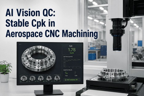
How Self-Tuning SPC Changes the Supervisor's Quality Model
Traditional SPC in aerospace CNC machining runs on static control limits set during process capability studies. These limits reflect the process capability at the time of the study — which may be months or years before current production. As tools wear, fixtures drift, and material batches vary, the real process variation changes. Static limits become either too tight (generating false alarms that operators learn to ignore) or too wide (missing real drift until it reaches the tolerance boundary). Self-tuning SPC eliminates this problem by recalculating control limits dynamically against the current process behaviour — tightening when the process is stable, widening when genuine variation increases, and always distinguishing between common-cause variation and assignable-cause events that require supervisor intervention.
Control Stage
Static SPC Behaviour
Self-Tuning SPC Behaviour
New Tool Run
Same limits as worn-tool run — limits too wide for current capability, missing early drift
Limits tighten to reflect new-tool process capability — catches tool-change-to-tool-change variation more sensitively
Mid-Life Tool Drift
Drift approaches static limit but no alert fires — operator unaware until batch CMM detects the shift
Self-tuning limit detects the trend against current baseline — supervisor alert fires 15–25 parts before the tolerance boundary
Material Batch Change
Static limits generate false alarms from genuine material-driven variation — operators desensitised to alerts
Self-tuning limits adjust to new material batch baseline — real drift still detected, false alarm rate drops below 5%
AS9100 Audit
Static limit rationale must be re-justified each audit cycle — process changes create documentation gaps
Self-tuning logic is documented with timestamped limit change events — each adjustment traceable to the process data that drove it
What the Supervisor Dashboard Shows — and When It Fires an Alert
The supervisor dashboard is designed around a single operating principle: the supervisor should never be surprised by a defect escape. Every alert fires before the condition produces an escape — based on trend data, not threshold breaches.
Dashboard Panel 01
Live Cell Quality Status — All Machines at Once
Every CNC cell feeding AI vision data displays a live quality status: green (in control), amber (trending toward limit), or red (limit breach or defect detected). Supervisors see the complete floor status on a single screen — not a machine-by-machine check, but a simultaneous view of all cells with a clear priority order for attention. An amber status requires monitoring. A red status requires immediate response. The alert reaches the supervisor's mobile device simultaneously with the dashboard update — no lag between detection and notification.
Supervisor action: Amber — review trend data. Red — inspect cell, authorise hold or parameter correction.
Dashboard Panel 02
Tool Life vs Quality Correlation — When to Change Before the Escape
Each cutting tool in the cell is tracked against its accumulated part count and the quality trend for the features it generates. The dashboard shows the relationship between tool life and surface finish or dimensional drift — surfacing the point in the tool life cycle where quality characteristics begin to drift toward the limit. Supervisors see a predicted tool change point based on observed quality data, not just a calendar-based interval — extending tool life where quality allows and preventing escapes where wear is accelerating faster than expected.
Supervisor action: Schedule tool change at quality-data-driven interval — not at fixed count that may be too early or too late.
Dashboard Panel 03
Defect Pareto by Feature and Machine — Where the Risk Is Concentrated
The Pareto view ranks defect findings by feature type, machine, and shift — showing supervisors where quality risk is concentrated across the floor. A surface finish defect recurring on the same bore feature across three machines points to a tooling specification issue. The same defect concentrated on one machine points to a machine condition issue. Without this cross-cell view, both patterns look like isolated incidents. With the Pareto, they are visible systemic issues that a supervisor can escalate to engineering before the next NCR cycle.
Supervisor action: Escalate Pareto findings to engineering as systemic quality input, not isolated reactive NCRs.
Dashboard Panel 04
AS9100 Part Records — Traceability at Every Serial Number
Every part inspected by the AI vision system receives an automated quality record — part serial number, inspection results for each monitored feature, the SPC value at time of inspection, defect findings with images, and supervisor disposition. The record links to the machine programme version, cutting tool lot, and material billet in use at the time. This is the traceability chain that AS9100 Clause 8.5.2 requires and that First Article Inspection (AS9102) documentation needs — generated automatically without manual data entry, and accessible for any part in any production run on demand.
Supervisor action: Export part record on demand for customer escapes, AS9100 audits, or FAIR submissions.
"
We were getting two or three surface finish NCRs per quarter from our major defence customer — always on the same bore feature, always discovered at their incoming inspection. We had no in-process data for surface finish. Every NCR investigation started from zero. After deploying AI vision on the cell, we found within six weeks that the escapes were consistently occurring in parts 45 to 60 of each tool run on that operation — a tool wear window we had never tracked against quality data before. We moved the tool change to part 40. The surface finish NCRs stopped. That was 14 months ago. We have not had a single escape on that feature since.
— Production Supervisor, Tier 1 Aerospace Machining — Structural and Engine Component Programme
Deploying AI Vision on an Aerospace CNC Cell: What the First 90 Days Looks Like
Deployment is structured to validate performance before the system becomes the primary quality record — so the supervisor team builds confidence in the AI inspection output through observed accuracy, not through management mandate.
Days
1–14
Inspection Specification and Camera Setup
Critical features identified from drawing and quality plan. Camera positions configured. Lighting validated for each feature type. AI model initialised on existing good-part and defective-part sample images. No production disruption.
Days
15–30
Shadow Mode Validation
AI vision runs in parallel with existing inspection. Every AI finding compared against CMM and manual check results. False positive and false negative rates documented. Supervisor team reviews outputs daily and provides feedback on edge cases. Model retrained on site-specific findings.
Days
31–60
Live Inspection Activation
AI vision becomes the primary in-process inspection record. Self-tuning SPC activated on validated features. Supervisor alert thresholds set based on shadow mode performance data. AS9100 part records begin generating automatically per part serial number.
Days
61–90
Scale and Optimise
Defect Pareto analysis across 30 days of live data identifies highest-impact features for expanded inspection coverage. Tool life correlation model refined with accumulated quality data. First AS9100 audit with AI-generated part records completed. CMM frequency reduced based on AI coverage evidence.
Conclusion
Aerospace CNC machining quality escapes are not caused by negligent inspection. They are caused by an inspection model — manual visual check and periodic batch CMM — that was never designed to catch the defect categories that actually drive NCRs at customer receipt: surface finish drift in the last third of tool life, chatter on fatigue-critical features, burrs at intersecting bores, and the slow dimensional creep that develops invisibly between tool changes. No manual inspection resource can economically check every feature on every part at the frequency and resolution that aerospace quality demands. AI vision does, at production speed, with zero fatigue, and with the AS9100-aligned part record that makes every finding traceable from detection to disposition.
For supervisors, the change is specific: instead of managing quality through end-of-batch review and NCR response, the dashboard shows what is drifting now, on which cell, driven by which parameter, before the first escape leaves the floor. The self-tuning SPC alerts arrive when intervention still prevents a defect — not when it documents one. The Pareto view reveals the systemic patterns that isolated NCR investigations never connect. And the automated part record removes the documentation burden that manual traceability places on every operator and inspection staff member on shift.
iFactory's AI vision inspection platform is built for aerospace CNC machining supervisors who need to prevent defects, not document them. Book a Demo to see the system operating on a CNC machining use case matched to your production profile, or talk to an expert about configuring AI vision for your specific cell, feature set, and AS9100 traceability requirements.
Frequently Asked Questions
The imaging environment is the first element configured during deployment. For machined metal surfaces, controlled coaxial and oblique lighting eliminates ambient variation and ensures consistent image quality across production shifts. For complex geometries — turbine blade profiles, compound-curved brackets, deep bore intersections — multi-angle camera configurations and structured light scanning provide full coverage of features that single-angle systems cannot reach. iFactory's deployment assessment defines the imaging configuration for each feature before installation, validating image quality against a representative production sample before the model training phase begins. The system is validated against your specific feature set and geometry before it generates a single inspection result. Talk to an expert about imaging configuration for your cell geometry.
Yes, for the feature categories where AI vision provides validated inspection coverage. The common pattern after AI vision deployment is to maintain CMM at first-off and tool change verification — its highest-value use — and reduce mid-run and end-of-batch sampling frequency on the features covered by in-process AI inspection. This is supported by AS9100 Rev D Clause 8.5.1, which requires in-process verification but does not mandate a specific technology. The AI-generated part record, with its per-feature inspection result and SPC value, constitutes an in-process verification record that satisfies clause requirements. Deployment documentation includes the evidence package needed to support the sampling frequency change through your internal change control process. Book a Demo to see how the AS9100 documentation outputs are structured for your quality plan.
Conventional SPC sets control limits from a capability study at a specific point in time — typically at process qualification. Those limits are fixed until a formal recalculation is authorised through the quality management system. In practice, this means control limits may be outdated by months or years when current production runs. Self-tuning SPC recalculates limits dynamically against the current rolling data window — typically the last 20 to 50 parts — using an algorithm that distinguishes between common-cause process variation (which should adjust the limits) and assignable-cause events (which should fire an alert, not adjust the limits). Every limit adjustment is logged with a timestamp, the data window that drove the change, and the statistical basis for the recalculation — creating an auditable record that demonstrates the limits are always current and justified. Talk to an expert about configuring self-tuning SPC for your key characteristics.
iFactory's part record structure links each inspection record to the production context data captured at the time of machining: CNC programme number and revision, cutting tool lot and part count at time of use, material billet or heat lot number, machine identifier, operator ID, and shift. This data is pulled from the CNC controller, tool management system, and MES at the time of each part cycle — no manual entry required. When a defect is identified and dispositioned, the disposition record attaches to the part serial number with the same context data, creating the complete traceability chain that AS9100 Clause 8.5.2 and AS9102 FAIR documentation require. For customer escape investigations, the record identifies exactly which batches, tool intervals, and programme versions were in use — enabling precise containment scoping rather than conservative over-containment. Book a Demo to see the traceability record structure configured for your AS9100 quality plan.
The Defect That Causes the NCR Is Already in Your Production Data. AI Vision Finds It Before the Customer Does.
iFactory's AI vision platform inspects 100% of aerospace CNC parts for surface finish, dimensional drift, chatter, burrs, and thermal damage — with self-tuning SPC alerts, tool-life quality correlation, and AS9100 traceability records generated automatically on every part your cells produce.