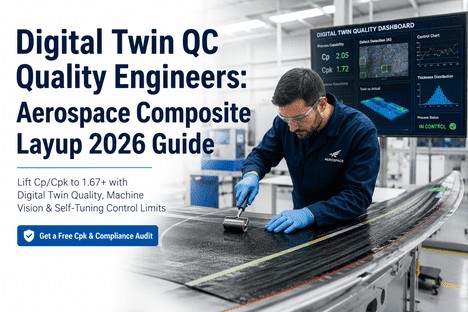
Ply 14 of a 32-ply carbon fibre panel. The layup head completes its pass. Visual inspection begins. The operator checks fibre orientation against the tolerance callout on the drawing — a 3-degree allowance on the 45° plies. A gap of 0.4mm exists between two tow courses. It is below the rejection threshold, but only just. The inspector signs off. The panel goes to cure. Forty-eight hours later, an ultrasonic C-scan reveals internal porosity at that location. The panel is scrapped. The cure cycle time, the layup time, the material cost, and the downstream slot on the autoclave are all gone. And the root cause — a tow placement deviation that was borderline on visual check — was never captured in a system that could have flagged it in real time, prevented the cure commitment, and stopped the repeat. This is the problem AI vision inspection solves in aerospace composite layup: catching what human inspection misses, at ply level, before the next process step locks the defect in.
Deep Learning Defect Detection · In-Process Ply Inspection · AS9100 SPC · Downtime Reduction
Every Missed Defect at Layup Becomes a Scrapped Panel After Cure. AI Vision Stops It at Ply Level.
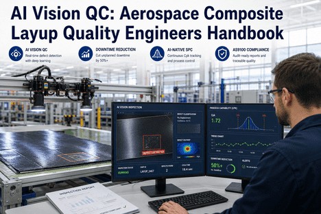
iFactory's AI vision inspection platform detects gaps, overlaps, fibre orientation deviations, FOD, and porosity precursors at every ply pass — generating AS9100-aligned SPC records and downtime-eliminating alerts before the cure cycle is committed.
$2.5B
AI-powered aerospace inspection market projected by 2034, up from $750M in 2024 — a 233% increase driven by scrap and downtime costs
27%
More defects detected by AI vision systems compared to manual inspection methods alone in aerospace composite inspection
50%
Reduction in inspection time achieved by GE Aerospace's AI-enhanced blade inspection tool — directly translating to unplanned downtime reduction
48 hrs
Typical aerospace autoclave cure cycle — the irreversible process step that locks in every undetected layup defect before it becomes scrap
The Defect Physics of Composite Layup: Why Human Inspection Cannot Keep Up
Composite layup defects are not always visible to the eye — and the ones that are visible are not always interpretable without data context. A 0.4mm gap between tow courses may be within tolerance on its own, but combined with a 2.1-degree fibre orientation deviation on the same ply, it represents a compound defect that will drive localised porosity under cure conditions. Manual inspection catches single-parameter observations. AI vision captures multi-parameter combinations — and that is the difference between detecting a defect and detecting a defect that will become a structural failure.
The Six Composite Layup Defect Types AI Vision Detects — and What Manual Inspection Misses
Structural Risk
Gaps Between Tow Courses
Tow separations create resin-rich zones that cure as localised porosity and discontinuities — reducing tensile and compressive strength. Even sub-threshold gaps accumulate across a laminate to compromise interlaminar shear strength in ways no single-ply inspection reveals.
AI detects: Gap width to ±0.05mm resolution, location mapping, accumulation trending across plies
Structural Risk
Tow Overlaps
Overlapping tow courses create thickness variations that alter local fibre volume fraction. Small overlaps can improve fibre continuity but larger overlaps cause resin starvation and interlaminar stress concentrations that initiate delamination under fatigue loading.
AI detects: Overlap dimension, position relative to ply boundary, sequence pattern across layers
AS9100 Critical
Fibre Orientation Deviation
Composite laminate strength depends entirely on the intended fibre orientation sequence — 0° plies carry axial load, ±45° plies handle shear, 90° plies resist transverse stress. A 3–5 degree orientation error on a structural ply can reduce allowable load capacity by up to 15% in the critical load direction.
AI detects: Orientation measurement to ±0.1°, deviation from nominal, out-of-tolerance alert per tow
Process Risk
Wrinkles and Out-of-Plane Defects
Steering curvature errors during AFP create wrinkle defects — out-of-plane distortions in the tow that become compressive stress concentrators under load. Wrinkles and bridging are among the most common AFP-generated defects and the hardest to detect through end-of-layup visual checks.
AI detects: 3D structured light scanning detects surface height deviation and wrinkle amplitude in real time
Contamination Risk
Foreign Object Debris (FOD)
Release film fragments, backing paper sections, fuzzballs, and contamination particles caught between plies prevent proper interlaminar bonding during cure. FOD is undetectable by post-cure NDT in most cases — the item is cured in place. AI vision is the only reliable detection point before the ply is covered by subsequent layup.
AI detects: Foreign material classification by texture signature, alert before next ply pass
Process Drift
Missing Tows and Low Tack
Missing tow courses create structural voids that cannot be recovered post-layup. Low tack between tow and substrate allows ply slippage under subsequent compaction — generating defects in layers that appeared correct at inspection. Both are driven by process parameter drift that continuous monitoring detects before accumulation.
AI detects: Tow count verification per pass, tack anomaly detection via optical signature change
In-Process Detection · Ply-Level Records · SPC Integration · AS9100 Compliance
A Defect Found at Ply 14 Costs a Repair. A Defect Found After Cure Costs a Panel.
iFactory's AI vision system inspects at every ply pass — generating a real-time defect map, SPC control chart, and AS9100-ready build record before the cure cycle is authorised.
Where Downtime Actually Comes From in Composite Layup — and Where AI Eliminates It
Unplanned downtime in composite layup operations does not always announce itself as a line stoppage. It appears as scrapped panels after cure, as rework cycles that push autoclave slots, as inspection holds waiting for quality disposition, and as repeat defect investigations that consume engineering time without resolving the root parameter. AI vision addresses each of these downtime sources differently — and the cumulative effect is the 50%+ reduction in inspection-linked downtime that advanced aerospace facilities are now reporting.
Downtime Source 01
Manual Inter-Ply Inspection Halts
Traditional quality control requires the AFP head to stop after each ply for a QA inspector to visually check the layup surface before the next ply pass is authorised. In a 30-ply structural panel, this creates 29 inspection hold points — each consuming 5 to 15 minutes depending on panel size and complexity. AI vision systems mounted on the AFP head inspect continuously during the layup pass itself, eliminating the hold entirely.
Manual: 29 inspection holds per panel
AI: Zero holds — inspection runs during layup
Downtime Source 02
Post-Cure Scrap and Autoclave Re-Runs
A panel that passes layup inspection but fails post-cure NDT has consumed the full cure cycle — typically 8 to 48 hours in an autoclave — plus all material and layup time. The autoclave slot cannot be recovered. AI vision prevents this by detecting the defect at ply level, before cure is committed. The intervention cost is a ply rework or layup restart — a fraction of the cost of a cured scrap panel.
Manual: Defect found after cure cycle
AI: Defect detected at ply — cure not committed
Downtime Source 03
Quality Disposition Holds and Engineering Review
When a borderline defect observation is made during manual inspection, the standard response is a quality hold — the panel cannot proceed until an engineering disposition is issued. This review may involve senior QA, design engineering, and the customer — taking hours to days. AI vision systems with SPC integration provide a documented measurement with statistical context, enabling disposition decisions based on data rather than inspector judgement under time pressure.
Manual: Disposition hold — hours to days
AI: SPC data enables rapid disposition with documented evidence
Downtime Source 04
Repeat Defect Investigation Without Root Cause
A gap defect recurring at the same location across multiple panels points to an AFP head parameter issue, a mould geometry variation, or a material batch characteristic. Without ply-level data from every panel, the engineering investigation starts from zero each time. AI vision accumulates a defect database across every panel and every ply — enabling pattern detection that identifies the root cause parameter before the third occurrence, not after the tenth.
Manual: Each occurrence investigated separately
AI: Cross-panel pattern detection identifies root cause from data
How iFactory's AI Vision System Integrates With the Composite Layup Workflow
The system operates in three connected layers — real-time ply inspection, SPC integration, and AS9100-aligned build record generation — each producing a different class of value for the operator, the quality team, and the audit function.
Layer 01
Real-Time Ply Inspection
Runs during layup pass — no production halt required
Camera arrays and structured light scanners mounted on the AFP head capture continuous imagery of each tow course as it is laid. Deep learning models process the image stream in real time — classifying gap width, overlap dimension, fibre orientation angle, surface height deviation, and any foreign material presence. Defects are flagged with their exact location on the ply coordinate system before the next pass begins. The operator receives a defect alert with location, type, and severity — not a post-pass summary, but a live finding during production.
Sub-millimetre gap detection
±0.1° orientation measurement
FOD classification during pass
Layer 02
Continuous SPC and Cpk Tracking
Process capability monitored across every ply and every panel
Every defect measurement feeds into the SPC control chart in real time — updating Cpk for gap width, fibre orientation, and overlap dimension across the current panel and the rolling production run. Operators see a live Cpk value for each quality characteristic, with control limits applied from the AS9100 process capability requirements. When a characteristic approaches a control limit — not after it breaches — the operator receives a process drift alert, enabling adjustment of AFP head parameters before out-of-tolerance production occurs. The multivariate ML layer identifies when two parameters drifting together predict an imminent defect cluster, surfacing the interaction that single-variable SPC cannot see.
Live Cpk per quality characteristic
Process drift alert before breach
Multivariate defect prediction
Layer 03
AS9100 Build Record Generation
Automated compliance documentation — no manual data entry required
Every panel receives a complete digital build record — ply-by-ply inspection findings, defect map with coordinates, SPC data for the production run, operator actions taken, and cure authorisation sign-off — generated automatically from the inspection data without manual documentation. The record is structured for AS9100 first article inspection and production approval requirements, and is exportable for customer delivery data packages, internal quality audits, and airworthiness authority submissions. When a defect is found and dispositioned, the disposition rationale attaches directly to the relevant ply in the build record — creating the traceability chain that regulators and customers require.
Ply-level defect map per panel
AS9100 FAI-ready data package
Disposition and cure authorisation trail
"
Before we deployed in-process AI vision, our inter-ply inspection holds were consuming 35 to 40 minutes per panel on complex structural parts. The inspector would check, sign the traveller, and the AFP cell would restart. Multiply that across a 28-ply fuselage skin and you're looking at nearly 17 hours of inspection time per panel — time the cell wasn't producing. The AI system runs during the pass. The cell doesn't stop. Our inspection-linked downtime on that programme dropped by over 60% in the first quarter, and we're catching defects we were missing before — particularly FOD between plies 8 and 12 on the curved sections where visual access was always poor.
— Quality Systems Manager, Tier 1 Aerostructures Facility — CFRP fuselage panel programme
Frequently Asked Questions
Conclusion
In aerospace composite layup, the cost of a defect is not linear with its severity — it is linear with when it is found. A gap detected during ply 14 is a rework. The same gap found after a 48-hour cure cycle is a scrapped panel, a lost autoclave slot, and a production delay that ripples across the programme schedule. AI vision inspection changes this cost structure entirely by moving detection from post-cure NDT to in-process ply inspection — finding what human eyes miss, at the resolution quality requires, without the production holds that manual inter-ply inspection demands. With AI-driven systems now detecting 27% more defects than manual methods and cutting inspection-linked downtime by 50% or more, the case for deployment is no longer about whether AI vision works — it is about how quickly it can be integrated into the layup cell that is generating preventable scrap today.
iFactory's AI vision inspection platform integrates with AFP and manual composite layup operations — delivering real-time defect detection, continuous SPC and Cpk tracking, and AS9100-aligned build records in a single operational layer. Book a Demo to see the system operating on a composite layup use case matched to your production profile, or Get In Touch to begin your deployment assessment.
The Defect That Costs the Most Is the One Locked Into the Panel Before Cure. AI Vision Finds It First.
iFactory detects gaps, overlaps, fibre orientation deviations, FOD, and wrinkles at every ply — with live SPC, AS9100 build records, and downtime-eliminating inspection built into your layup workflow from day one.