A vision model that flags belt misalignment or a hot clinker fragment two seconds after it happens is not monitoring the conveyor, it is documenting what already went wrong. Cloud-based inference adds anywhere from four hundred to twelve hundred milliseconds of round-trip network latency to every frame, and on a cement conveyor running continuously through dust, heat shimmer, and vibration, that delay is the gap between catching a spillage event early and cleaning up after a belt fire. Moving inference to the edge, a GPU running directly at the plant, is not an incremental upgrade, it is the only architecture that matches the speed cement conveyor conditions actually demand, which is exactly the deployment our engineering team scopes for every plant that asks how to get real-time detection rather than a delayed alert.
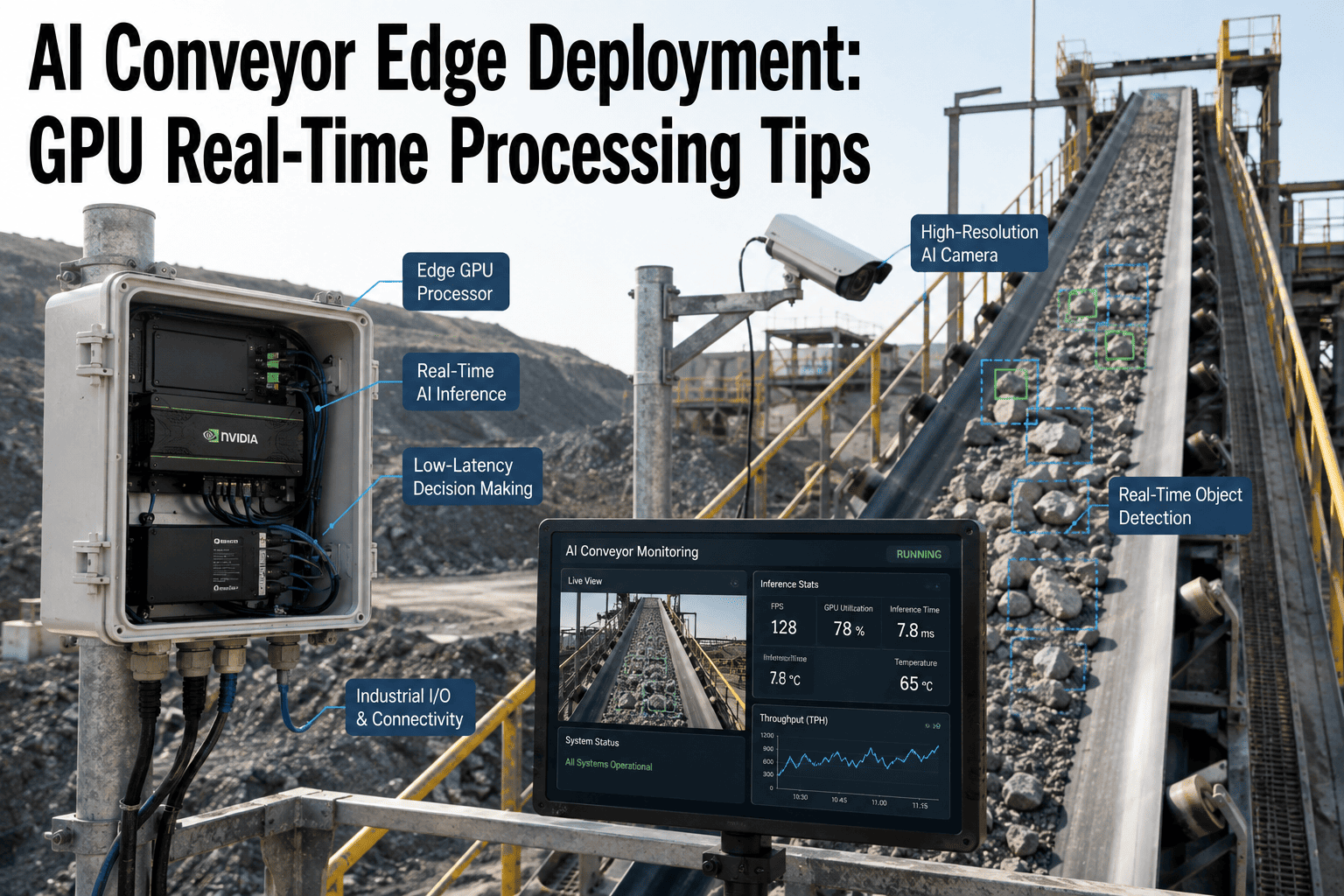
AI Conveyor Edge Deployment: GPU Real-Time Processing Tips
GPU selection, model optimization, and connectivity architecture for sub-second belt monitoring in cement plant conditions, dust, heat, and vibration included.
Why Cloud Inference Fails a Conveyor Monitoring Use Case
The architectural default for a lot of early industrial AI deployments was straightforward: stream camera feeds to a cloud data center, run the model there, send the result back to the plant. That model works acceptably for use cases where a delay of a second or more is tolerable, but a cement conveyor is not that use case. A belt tear propagates, spilled material accumulates at a transfer point, or a piece of hot clinker sits on the belt surface, all continuing to develop during the exact window a cloud round trip consumes. By the time a cloud-processed alert reaches the control room, the condition it is describing has already moved past the point where early intervention was possible.
There is a second problem beyond latency that plants discover once they try to run this at scale: network dependency and bandwidth. Streaming continuous high-resolution video from every camera on every conveyor to an external data center consumes serious bandwidth, and any network interruption, common enough in a plant environment with heavy electrical equipment nearby, means the monitoring system goes blind exactly when a fault might be occurring. Edge inference removes both problems simultaneously, since the GPU processing the video feed sits in the same building as the camera, with a physical connection measured in meters rather than a network path measured in hundreds of miles.
Data sovereignty is a third consideration that matters more to some operators than others, but it is worth naming explicitly. Streaming continuous production footage to an external cloud provider means process imagery leaves the plant's perimeter by design, and for facilities with strict data handling requirements or a preference for keeping operational visual data entirely within their own infrastructure, edge deployment is the only architecture that satisfies that requirement while still delivering the same detection capability. This has become enough of a priority industry-wide that the shift toward local inference over cloud processing is now the dominant deployment pattern for new industrial AI rollouts rather than a niche preference.
The Inference Path, Cloud Versus Edge
The physical distance the signal travels is the entire explanation for the latency gap. Edge architecture keeps every hop inside the plant's own network, which is why the total path completes in tens of milliseconds instead of hundreds.
Selecting the Right GPU for Your Camera Count
GPU selection is not a single choice, it is a sizing exercise driven by how many camera feeds need simultaneous processing and how much compute headroom each detection model requires. Over-specifying wastes capital on unused capacity, and under-specifying means dropped frames or queued inference, which reintroduces the same latency problem edge deployment was meant to solve in the first place. The tiers below reflect the practical range most cement plant deployments fall into.
Entry Tier
Roughly 40 to 70 TOPS INT8
Suited to a single conveyor or a small cluster of two to four cameras running one detection model, such as a pilot deployment on the highest-priority belt before wider rollout.
Mid Tier
Roughly 100 to 275 TOPS INT8
The common choice for a process unit running four to eight camera feeds with concurrent workloads, belt tracking, spillage detection, and thermal monitoring near the clinker cooler, all processed on one appliance.
High Tier
275+ TOPS, multi-GPU or higher-compute platforms
Reserved for plant-wide deployments covering kilns, mills, crushers, and multiple conveyor lines simultaneously from a single centralized compute node, or facilities running higher-resolution thermal-visual fusion across many zones at once.
A useful rule of thumb when sizing: each additional camera running a standard object detection model at production frame rates adds a predictable compute load, and running thermal-visual fusion, common in cement plants for hot clinker detection, roughly doubles the compute requirement per camera compared with visible-light detection alone. Confirming your camera count, resolution, and detection model mix against a specific TOPS requirement is worth doing with an engineer before purchase, since the gap between an adequately sized and an undersized system only shows up once the plant is running every camera concurrently under real production load.
Model Optimization: Getting Full-Precision Accuracy Onto Edge Hardware
A model trained and validated on a full-precision server-class GPU cannot simply be copied onto an edge device and expected to run at the same speed. Getting a detection model to run fast enough for real-time inference on compact edge hardware requires a deliberate optimization step, and understanding what happens during that step matters for anyone evaluating whether a vendor's accuracy claims will actually hold up in production.
Quantization
Full-precision model weights, typically 32-bit floating point, are converted to a lower-precision format, commonly 16-bit or 8-bit integer, which reduces memory footprint and increases inference speed substantially on edge hardware. This step can reduce model accuracy by a small margin, commonly in the range of half a percent to two percent, which is why the next step is not optional.
Compilation for the Target Hardware
The quantized model is compiled specifically for the GPU architecture it will run on, using the hardware vendor's optimization toolchain, so the model's operations map efficiently onto that specific chip's execution engine rather than running as a generic, unoptimized workload.
Validation Against a Held-Out Test Set
The compiled, edge-optimized model is run against a validation dataset representing real production conditions, varying dust levels, lighting, belt speed, and material types, confirming that accuracy after optimization still meets the threshold required before any fleet-wide deployment decision.
Staged Rollout With Performance Monitoring
The validated model deploys first to a single conveyor, then expands to a full process unit, then to the wider plant, with detection accuracy and latency monitored at each stage rather than pushing a single fleet-wide update all at once.
See Real-Time Detection Running on Your Own Conveyor Feed
Book a session and iFactory will walk through what edge inference latency looks like on your specific camera setup and conveyor layout, using footage from a facility similar to yours.
Building for Cement Plant Conditions, Not a Clean Lab
Hardware and models validated in a controlled test environment routinely underperform once deployed in the actual conditions surrounding a cement conveyor, which is why treating environmental hardening as a separate checklist rather than an afterthought matters as much as GPU selection itself. Dust, heat, and vibration are not occasional edge cases in a cement plant, they are the baseline operating condition every piece of hardware and every model has to perform under continuously.
Dust Ingress
Cement dust infiltrates connectors, cooling systems, and camera lenses continuously. Edge GPU enclosures rated IP65 or higher, and camera housings using positive-pressure filtered air across the lens, are the practical baseline rather than an upgrade option.
Thermal Extremes
Zones near the kiln and clinker cooler run at elevated ambient temperatures, and standard commercial GPU hardware built for a narrow ten to thirty five degree range fails quickly in this environment. Wide-temperature-rated hardware and fanless or reinforced cooling designs are required.
Continuous Vibration
Conveyor drives and crushing equipment generate sustained vibration that causes mechanical fatigue in standard hardware over time. Anti-vibration mounting, isolation dampers, and solid-state storage rather than spinning drives reduce transmitted vibration substantially.
Heat Shimmer and Low Visibility
Visual distortion from heat shimmer near hot material, and reduced visibility in dust-heavy zones, degrades detection accuracy for models trained only on clean visual data. Detection models trained specifically on cement plant visual conditions, and dual-mode thermal plus visible cameras, maintain accuracy where visible light alone falls short.
Connectivity Architecture: Wiring the Plant Correctly
GPU compute and camera hardware alone do not make an edge deployment work, the network architecture connecting cameras to the edge compute node and the edge node to plant systems has to be designed deliberately. The most common mistake at this layer is treating vision traffic the same as ordinary plant network traffic, which creates congestion that degrades the very latency advantage the edge deployment was built to capture.
| Layer | Typical Approach | Why It Matters |
|---|---|---|
| Camera to edge GPU | Wired Ethernet, PoE where practical, dedicated cabling | Sub-5 millisecond local network latency, avoids wireless interference in an electrically noisy plant |
| Traffic segmentation | Dedicated VLAN for vision traffic, separate from control network | Prevents large video streams from disrupting time-critical PLC and control communications |
| Edge to CMMS and control room | Structured protocols such as OPC-UA and Modbus, REST API connectors | Alerts and structured fault data reach existing systems without custom middleware |
| Redundancy and failover | Redundant power supplies, local storage buffering during network interruption | Monitoring continues uninterrupted through brief network or power disruptions common in plant environments |
What Sub-Second Detection Actually Catches
The practical value of closing the latency gap is best understood through what specifically becomes catchable at edge speed that was not catchable at cloud speed. These are not hypothetical scenarios, they are the specific conveyor fault categories that develop on a timescale where a few hundred milliseconds of added delay is the difference between an early warning and a cleanup job.
Hot Clinker on the Belt
Thermal-visual fusion identifies clinker fragments exceeding safe belt temperature as they discharge from the cooler, triggering an alert before accumulated heat ignites the belt or surrounding dust, a fault that can develop into a fire risk within seconds of the first detection window.
Belt Misalignment and Tracking Drift
Uneven loading patterns create edge wear and spillage that worsens progressively. Catching the earliest visible drift at edge speed allows correction before the belt reaches the point of active material spillage at transfer points.
Material Spillage Accumulation
Spillage at transfer points and around return rollers compounds quickly once it starts, and real-time detection quantifies accumulation volume as a trend rather than discovering the problem only after it becomes a housekeeping and combustible-dust hazard.
Belt Tears and Surface Wear
Impact damage from oversized material and abrasive wear progresses along the belt surface, and early detection at edge speed gives maintenance a window to schedule repair before a small tear propagates into a full belt failure that stops production.
From Detection to Work Order in Real Time
Edge inference speed only creates value if the resulting detection actually reaches the people who act on it without another layer of delay. A well-architected deployment closes this loop completely, connecting the GPU's detection output directly into the plant's maintenance system rather than stopping at a dashboard alert that still requires someone to notice, interpret, and manually create a work order.
Sizing Bandwidth and Storage at the Edge Node
GPU compute gets most of the attention in an edge deployment conversation, but bandwidth and storage sizing at the edge node itself are just as capable of becoming the bottleneck if they are treated as an afterthought. Every camera feed processed locally still needs to move from the camera to the GPU, and while that local hop is dramatically shorter than a cloud round trip, it still consumes real network capacity, particularly once a facility scales from a single pilot camera to a full process unit running six or eight feeds concurrently at production resolution.
Storage sizing follows a similar logic. Most deployments do not need to retain every raw frame indefinitely, but they do need to retain enough recent footage and flagged event clips to support root cause analysis when a maintenance team wants to review what led up to a detected fault. Sizing local storage around a defined retention window, commonly a rolling period measured in weeks for routine footage and a longer archive specifically for flagged fault events, keeps the edge node's storage requirement predictable rather than growing without bound as camera count increases across the plant.
Common Sizing Mistakes That Undermine Real-Time Performance
A handful of avoidable planning mistakes account for most of the edge deployments that fail to deliver the sub-second performance the architecture is capable of. Knowing these in advance is considerably cheaper than discovering them after hardware is already installed and running below expectation on the production floor.
Sizing for Today's Camera Count Only
Plants that specify GPU compute for their current camera count, without headroom for the additional cameras a successful pilot typically leads to, end up needing a hardware upgrade within the first year rather than the several years a properly sized appliance should last.
Skipping Site-Specific Model Validation
Deploying a model validated only on generic factory imagery, rather than validated against your specific plant's dust levels, lighting, and material types, is one of the most common causes of underperforming accuracy once a system goes live in actual cement plant conditions.
Mixing Vision Traffic With Control Traffic
Running high-bandwidth camera streams on the same network segment as time-critical PLC and control communications creates exactly the kind of congestion-driven latency the edge deployment was meant to eliminate in the first place.
Treating Environmental Hardening as Optional
Installing standard commercial-grade GPU hardware in a cement plant environment without the appropriate ingress protection and thermal rating is a reliable way to see premature hardware failure within months rather than the years of service life properly rated equipment delivers.
Frequently Asked Questions
Can we use our existing conveyor cameras, or do we need to replace them for edge AI deployment?
Most deployments reuse existing camera infrastructure wherever it meets the resolution and positioning requirements for reliable detection. The edge GPU compute unit connects to your current camera feeds rather than requiring a full camera replacement, which significantly reduces both the cost and the disruption of getting a deployment live. Where existing cameras fall short, typically insufficient resolution, poor positioning relative to the detection target, or no thermal capability where thermal monitoring is needed, targeted additions are made at those specific high-priority points rather than replacing coverage that already works. Reviewing your current camera inventory against detection requirements with an engineer is the fastest way to see what carries over.
How much does quantizing a model for edge deployment actually reduce accuracy?
Quantization, converting a full-precision model to a lower-precision format for faster edge inference, typically reduces accuracy by a small margin, commonly in the range of half a percent to two percent depending on the model architecture and the specific quantization method used. This is why validation against a held-out test set representing real production conditions is a mandatory step before any edge-optimized model goes into production, not an optional check. A properly validated and optimized model for cement plant conditions commonly still achieves detection accuracy above 95 percent even in dust-heavy and low-visibility zones, which is well within the range needed for reliable fault detection.
What GPU compute do we actually need for a plant with multiple conveyors and process units?
Compute requirements scale with camera count, resolution, and how many detection workloads run concurrently on each feed, so there is no single answer independent of your specific layout. A small pilot on one high-priority conveyor typically runs comfortably on an entry-tier edge GPU, while a full process unit running several cameras with concurrent belt tracking, spillage detection, and thermal monitoring for hot clinker generally calls for a mid-tier appliance, and plant-wide coverage across kilns, mills, and multiple conveyor lines moves into higher-compute or multi-GPU territory. The only reliable way to size this correctly is mapping your actual camera count and detection requirements against GPU throughput, which is exactly what a deployment scoping session with our team works through before any hardware is ordered.
How does the edge system keep working if the plant network goes down?
A properly architected edge deployment is designed specifically to keep local inference running independent of the broader plant or external network, since the camera-to-GPU connection is a local, direct link rather than one that routes through the wider network. Detection and monitoring continue uninterrupted through a network interruption, though alerts reaching the CMMS or control room may queue locally and sync once connectivity restores, depending on how the integration layer is configured. This resilience is one of the structural advantages edge architecture has over cloud-dependent monitoring, which goes completely blind the moment its network connection drops.
How long does a typical edge deployment take from decision to live monitoring?
Where existing camera infrastructure covers the required monitoring points, many plants go live on a pilot conveyor within a single production shift once the edge GPU appliance is installed and models are validated for that site's specific conditions. A broader rollout covering multiple process units and full plant coverage typically follows a staged timeline over several weeks, expanding camera coverage and validating detection accuracy at each stage before scaling further. Turnkey deployments that include pre-configured hardware shipped ready to rack commonly target live production inference within 6 to 12 weeks from hardware delivery, and confirming a realistic timeline for your specific facility is best done directly with an engineer during a scoping call.
Get Your Edge Deployment Scoped Before You Buy Hardware
GPU sizing, camera coverage, and network architecture all need to match your specific conveyor layout and plant conditions before a single unit is ordered. iFactory's engineers will scope the full deployment against your existing camera infrastructure and process unit count.