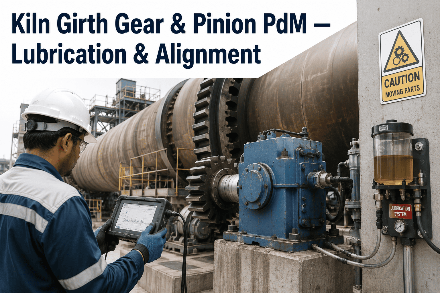
A cracked tooth root on a kiln girth gear rarely announces itself with a bang. It shows up first as a faint whine in the drive train, a half-degree rise in mesh temperature, or a vibration reading that a busy technician logs and moves past. By the time the crack propagates far enough to be obvious on a walkdown, the plant is no longer choosing between inspection and replacement planning — it is choosing between an emergency shutdown at premium contractor rates or limping the kiln at reduced speed until a spare arrives. Girth gears are among the longest lead-time items in a cement plant, often six to twelve months from order to installed and aligned, which means the inspection program has to catch degradation while there is still enough runway to plan the purchase. You can book a demo to see how iFactory turns girth gear condition data into a procurement timeline your plant can actually hit.
CEMENT KILN RELIABILITY · GIRTH GEAR CONDITION MONITORING · REPLACEMENT PLANNING
Catch Girth Gear Wear While You Still Have Time to Order the Part
iFactory tracks tooth wear trends, crack indications, and backlash readings against your gear's remaining useful life, converting a slow-moving mechanical asset into a schedulable procurement decision instead of a shutdown surprise.
6-12
Months typical lead time for a replacement girth gear casting
90%+
Of premature girth gear failures trace back to a handful of recurring wear modes
14+
Days of unplanned kiln downtime when a gear fails without warning
0.1mm
Per meter of face-width misalignment that can cut fatigue life by more than half
FAILURE MODES
The Handful of Wear Patterns Behind Nearly Every Girth Gear Replacement
Girth gears rarely fail from a single dramatic event. They fail because a small deviation in alignment, lubrication, or load distribution is left uncorrected long enough for fatigue to do its work. Understanding which pattern is developing on your kiln tells you how much runway you actually have.
Tooth Root Fatigue Cracking
Cyclic load variation from axial run-out concentrates stress at the root fillet with every revolution. On gears over four meters in diameter, this is the leading driver of cracking that ultimately forces an emergency replacement rather than a planned one.
Edge Loading from Misalignment
When the pinion and girth gear are out of parallel, load concentrates on one edge of the tooth face instead of spreading evenly across it. This shortens fatigue life dramatically and is one of the few failure modes that a monthly alignment check can catch before any metal damage occurs.
Pitting and Spalling
Repeated contact stress below the tooth surface eventually causes flakes of material to break away from the working flank. Early-stage pitting is a maintenance item; widespread spalling across multiple teeth is a replacement trigger.
Lubrication Film Breakdown
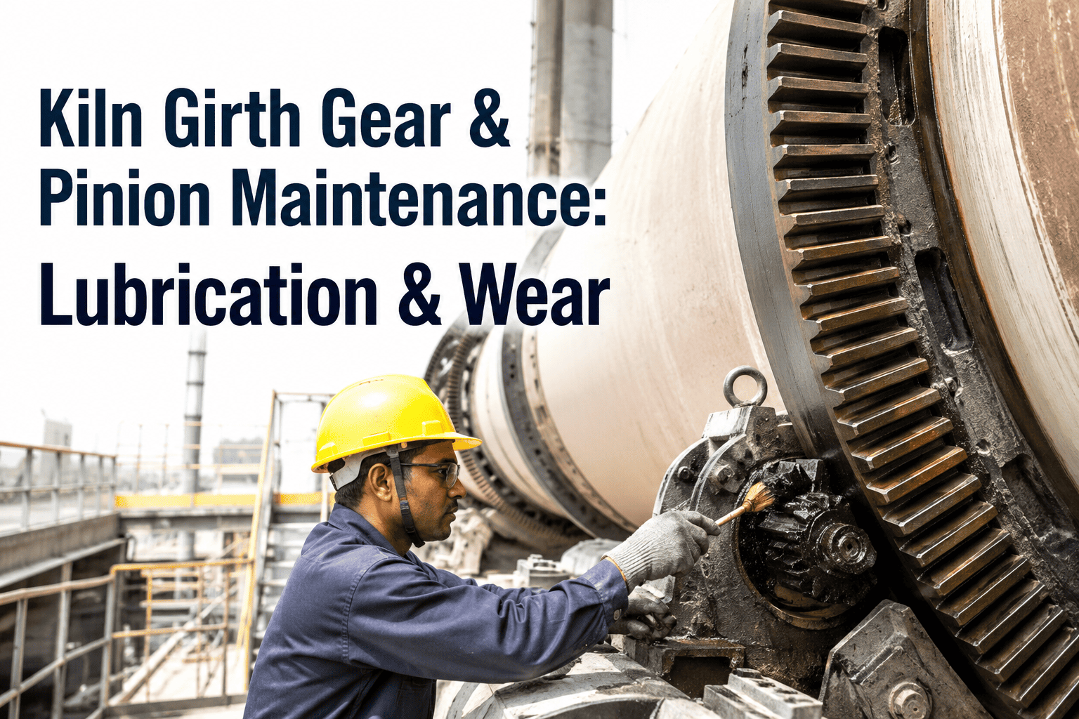
Open gear lubricant that is too thin, contaminated with kiln dust, or applied inconsistently allows metal-to-metal contact at the mesh point. This accelerates every other wear mode on this list and is often the true root cause behind a gear that "failed early."
Backlash Drift
As teeth wear, the clearance between the pinion and girth gear increases beyond specification. Excess backlash shows up as impact loading and noise long before it becomes a safety issue, making it one of the earliest measurable indicators of cumulative wear.
INSPECTION METHOD STACK
What a Complete Girth Gear Condition Assessment Actually Measures
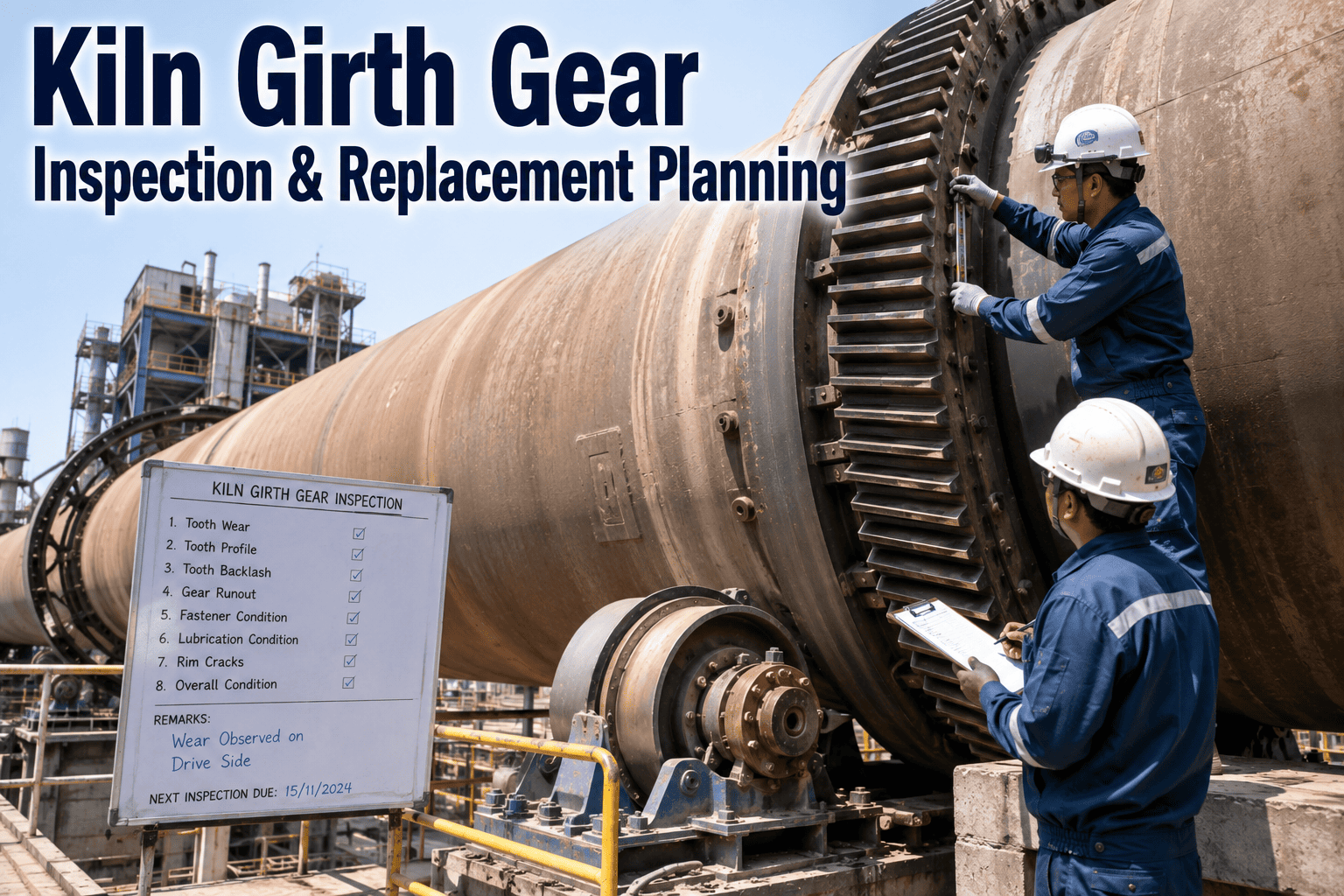
A visual walkdown alone will miss subsurface cracking and will not tell you how fast a measured deviation is trending. A complete assessment layers several inspection methods, each catching a different failure mode at a different stage of development.
01
Visual and Boroscope Survey
A tooth-by-tooth visual pass, ideally with the kiln indexed through a full revolution via the inching drive, documents surface condition, coating consistency, and any visible spalling or discoloration that indicates overheating at the mesh.
02
Tooth Profile and Wear Measurement
Gear tooth calipers or profile gauges measure remaining tooth thickness against the original design profile, generating a quantified wear trend that can be plotted against previous shutdowns rather than relying on a subjective visual call.
03
Surface and Subsurface Crack Detection
Magnetic particle inspection and eddy-current surface arrays detect surface-breaking flaws at the addendum, dedendum, and root that are invisible to the naked eye, with model-based sizing methods used to determine whether a found crack is stable or propagating.
04
Backlash and Run-Out Verification
Dial indicator readings at four positions ninety degrees apart establish radial and axial run-out, while feeler gauge or dial checks at the mesh confirm backlash is within the manufacturer's tolerance band.
05
Alignment Verification
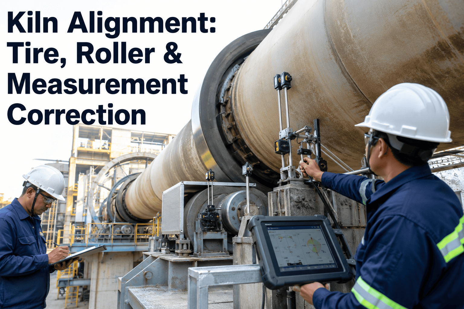
Laser alignment or marking compound contact patterns confirm the pinion and girth gear are parallel across the full face width, isolating the single most common root cause of accelerated, uneven wear.
06
Vibration and Thermal Trending
Accelerometers and infrared thermal mapping at the mesh interface catch gear mesh harmonics and localized temperature rise between planned shutdowns, extending your visibility into the gap between formal inspections.
Turn Every Gear Reading Into a Trend Your Reliability Team Can Act On
iFactory logs tooth wear measurements, crack findings, and backlash readings against your gear's history so degradation shows up as a trend line, not a surprise at the next shutdown.
OVERHAUL OR REPLACE
The Decision Framework: Repair the Gear or Order a New One
Not every crack or wear finding means a full gear replacement. The decision comes down to four factors, and getting the call wrong in either direction is expensive — either through a premature capital purchase or through pushing a compromised gear past the point where repair is still viable.
REPLACEMENT PLANNING TIMELINE
Working Backward from a Six-to-Twelve Month Casting Lead Time
Once a condition assessment points toward replacement, the procurement clock starts immediately. Girth gears are cast, machined, and heat-treated to order in most cases, and the timeline below reflects the sequence a plant needs to hit to avoid an unplanned stop.
Month 0-1
Condition Report and Capital Approval
Compiled wear measurements, crack sizing data, and trend history are packaged into a capital request. Plants with a documented inspection history move through approval faster because the case for replacement is already quantified rather than argued from a single visual finding.
Month 1-2
Specification and Foundry Selection
Exact dimensions, module, material grade, and mounting details are confirmed against the existing kiln shell and drive assembly. Segmented gears for large-diameter kilns require additional coordination on joint design and match-marking.
Month 2-9
Casting, Machining, and Quality Verification
This is the bulk of the lead time and the phase where delays most often occur. Casting defects, foundry backlogs, and heat-treatment scheduling are the usual culprits, which is why plants that start this process reactively often see the window stretch well past the initial estimate.
Month 9-11
Shipping, Rigging Plan, and Shutdown Scheduling
Segmented gears are shipped and staged well ahead of the outage. Rigging and crane plans for a component that can weigh well over the capacity of standard plant equipment are finalized in parallel with the shutdown scope for every other job planned in the same window.
Month 11-12
Installation, Alignment, and Startup
Segment installation, bolt torque sequencing, and precision alignment are completed during the planned outage, followed by a controlled startup and a first-run inspection to confirm mesh contact pattern before returning to full load.
COST OF GETTING THE TIMING WRONG
The Price Difference Between a Planned Order and an Emergency One
The financial gap between catching a girth gear problem early and discovering it at failure is not incremental — it is an order of magnitude, and it compounds every week the kiln sits idle waiting on a part that was never ordered in time.
Planned Replacement
Standard foundry rates, coordinated with an existing shutdown window, no premium freight, no expedited machining fees.
Reactive Replacement
Rush casting surcharges, expedited shipping, and a kiln running at reduced capacity or fully stopped while the plant waits on a part it should have ordered months earlier.
Catastrophic Failure
Secondary damage to the pinion, drive motor, or shell mounting, an unplanned stop measured in weeks rather than days, and a procurement process negotiated from the weakest possible position.
COMMON INSPECTION MISTAKES
Where Girth Gear Inspection Programs Quietly Fail
Most plants that get caught out by a girth gear failure were not skipping inspections entirely. They were running an inspection program with a gap in it, and the gap is usually one of the patterns below.
Treating a Visual Pass as a Complete Assessment
A tooth-by-tooth visual walkdown catches surface spalling and obvious coating loss, but it cannot see a subsurface crack forming at the root. Plants that rely on visual inspection alone routinely miss the failure mode that causes the most catastrophic downtime.
No Baseline to Compare Against
A single wear measurement tells you the current state. It does not tell you whether the gear is wearing at a rate of a few thousandths of an inch per year or accelerating toward the condemning limit. Without a documented baseline from the previous shutdown, every new reading is evaluated in isolation.
Skipping the Inching Drive Full Revolution
Inspecting only the teeth accessible from a fixed platform position leaves the majority of the gear unexamined. A full revolution through the inching drive during the inspection window is what actually confirms the whole gear, not just the visible arc.
Deferring Alignment Checks to "When There Is Time"
Alignment verification is often the first task cut when a shutdown runs long, yet misalignment is the single most common driver of accelerated, uneven wear. Deferring it repeatedly compounds the very problem the next inspection is meant to catch.
RUNNING THE KILN WHILE YOU WAIT
Interim Measures for a Kiln Waiting on Its Replacement Gear
A twelve-month casting lead time does not mean the kiln has to run unmanaged for a year. Plants operating with a known wear or crack finding typically layer in additional controls to buy time safely while the new gear moves through procurement.
01
Tightened Monitoring Interval
Vibration and thermal trending intervals are shortened from monthly to weekly once a confirmed finding is being tracked, so any acceleration in the wear rate is caught quickly rather than at the next scheduled reading.
02
Lubrication Film Reinforcement
Open gear lubricant application frequency and film thickness are often increased on a compromised gear, since reducing metal-to-metal contact at the mesh directly slows the progression of surface wear and pitting.
03
Load and Speed Management
Where production planning allows it, some plants moderate kiln speed or feed rate slightly to reduce peak load on a gear with a known crack indication, trading a small output reduction for additional service life margin.
04
Contingency Rigging Plan
Crane availability, rigging plans, and outage scope are pre-staged well ahead of the expected delivery date, so an early or unexpected gear arrival does not sit in storage waiting for a shutdown window to open.
BUILDING THE RECORD
Why a Digital Inspection History Changes the Replacement Conversation
The single biggest difference between plants that replace girth gears on their own schedule and plants that replace them in a panic is not the quality of any one inspection. It is whether that inspection connects to the ones before it. A wear measurement from this shutdown means little without the reading from the last one to establish a rate. A crack finding is far more actionable when it can be compared against a prior scan showing the same tooth was clean eighteen months earlier. Paper inspection sheets stored in a shutdown binder rarely get pulled back out and compared; a digital record that plots every reading against its history does that comparison automatically, and it is what turns a girth gear replacement request from a judgment call into a data-backed capital decision that moves through approval faster.
FREQUENTLY ASKED QUESTIONS
Girth Gear Inspection and Replacement Questions from Cement Reliability Teams
How often should a full girth gear condition assessment be performed?
Most cement plants schedule a comprehensive assessment, including crack detection and profile measurement, during every major planned kiln shutdown, typically on a one to two year cycle depending on kiln age and duty. Between shutdowns, monthly functional checks including backlash spot-checks and a visual pass through the inching drive catch developing problems without requiring a full stop. Plants running kilns past fifteen years of service, or those that have experienced prior misalignment events, often move to a tighter interval. You can
book a demo to see how an inspection cadence maps onto your specific kiln history.
Can a girth gear be repaired in place instead of replaced?
Localized repairs such as weld build-up on a worn tooth flank or crack arrest drilling are viable in specific cases, but they are a temporary measure rather than a substitute for replacement once wear approaches the condemning limit or cracking has reached the root. The decision depends heavily on gear material, crack location, and how much service life the plant needs to bridge before a new casting can be delivered. Our
support team can walk through the specific repair-versus-replace criteria that apply to your gear type.
What causes a girth gear to wear unevenly across its face width?
Uneven wear almost always traces back to alignment between the pinion and girth gear. Even a small deviation from parallel concentrates the transmitted load on one edge of the tooth face instead of distributing it evenly, and that concentrated loading accelerates fatigue on the loaded edge while the opposite edge shows comparatively little wear. Shell distortion, foundation settling, and thermal expansion differences between the kiln shell and support structure can all introduce this kind of misalignment over time, which is why alignment verification is a standard part of every planned assessment.
How do we justify the capital cost of a girth gear replacement to plant leadership?
The strongest justification is a documented wear and crack trend that shows the gear approaching its condemning limit on a predictable timeline, paired with the lead time required to order and install a replacement without an unplanned stop. Framing the request around the cost difference between a planned outage and an emergency failure, rather than the raw cost of the gear itself, tends to move capital requests through approval faster because it quantifies the downside of waiting. Documented, timestamped inspection records also support any warranty or insurance claim tied to the failure.
What is the difference between a single-piece and a segmented girth gear for replacement planning?
Girth gears above a certain diameter are manufactured in segments, typically two to four pieces, bolted together around the kiln shell, largely because a single-piece casting of that size becomes impractical to cast, machine, transport, and install. Segmented gears add joint design and match-marking considerations to the specification phase and require careful sequencing during installation to maintain concentricity, but they do not materially change the overall lead time compared to a single-piece casting of similar diameter. Rigging and crane capacity planning should account for handling individual segments rather than the full assembled weight in one lift.
Give Your Girth Gear Replacement Project a Twelve-Month Head Start
iFactory tracks the wear, crack, and alignment data your capital request needs and flags when a gear's trend line is heading toward replacement territory, so procurement starts on your timeline instead of the failure's.