A motor winding failure is preceded by a measurable insulation resistance decline that can be tracked for months before it becomes a trip event, and a broken rotor bar produces a distinctive current signature long before it causes a vibration problem anyone would notice by hand. Cement plants run hundreds of motors across mills, fans, conveyors, and crushers, and most of them are checked only when they trip or when an annual insulation test happens to be scheduled. Book a session with the iFactory reliability team to see how continuous motor current signature analysis, thermal imaging, and insulation trending catch electrical faults while there is still time to plan the repair.
Equipment Health · Motor Health Monitoring
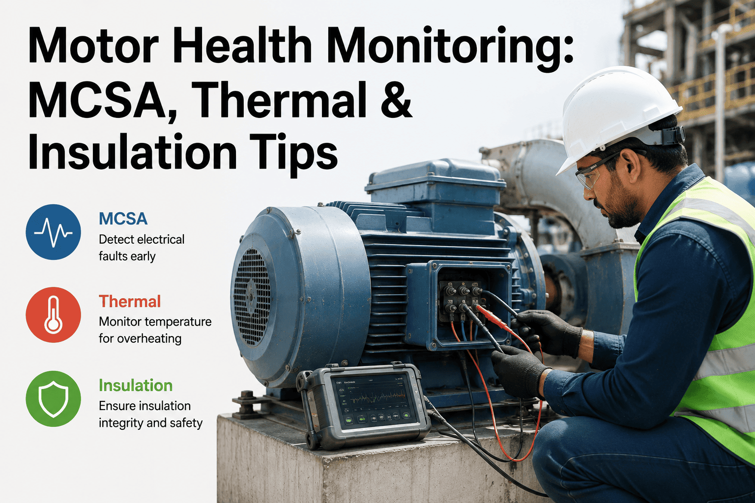
Motor Health Monitoring: Current Signature Analysis, Thermal Imaging, and Insulation Resistance
Rotor bar fault detection, stator winding degradation tracking, and bearing condition assessment for cement plant motors — mill drives, fan motors, conveyor drives, and crusher motors — combined into one continuous monitoring programme.
Motor Failure Anatomy
Where Motor Failures Actually Originate — and Which Test Catches Each One
Motor failure statistics across industrial plants consistently show the same distribution: a large share of failures originate in the bearings, a substantial share in the stator winding insulation, and a smaller but disproportionately disruptive share in the rotor itself. Each failure origin produces a different early signature, detectable by a different monitoring method — which is why single-method motor monitoring, whether that method is vibration alone or insulation testing alone, leaves real gaps in coverage.
40–50%
Bearing failures
Detected by: vibration analysis, thermal imaging
30–40%
Stator winding failures
Detected by: insulation resistance trending, MCSA
5–10%
Rotor bar failures
Detected by: motor current signature analysis
Remainder
External / mechanical causes
Detected by: thermal imaging, load and alignment checks
Motor Current Signature Analysis
How MCSA Detects Rotor and Stator Faults From the Electrical Supply Alone
Motor current signature analysis reads the electrical current drawn by the motor and looks for characteristic sideband frequencies that appear around the fundamental line frequency when specific mechanical or electrical faults are present. The significant advantage of MCSA is that it requires no physical access to the motor beyond the supply cabinet — no shaft-mounted sensor, no direct contact with rotating parts — which makes it practical to deploy across a large motor population without individual sensor installation on every motor housing.
Broken rotor bar detection
A broken or cracked rotor bar produces distinctive sidebands spaced at twice the slip frequency around the line frequency, visible in the current spectrum well before the fault produces a noticeable vibration or performance change.
Rotor eccentricity detection
Static or dynamic air gap eccentricity between rotor and stator produces its own current sideband pattern, often an early indicator of bearing wear or manufacturing tolerance issues before mechanical symptoms appear.
Stator winding fault detection
Early-stage turn-to-turn shorts in the stator winding create current imbalance and harmonic distortion patterns detectable by MCSA before the fault progresses to a phase-to-ground event that trips the motor.
Load and bearing signature
Mechanical load variation and certain bearing fault frequencies also modulate the current signature, allowing MCSA to serve as a secondary detection method that complements dedicated vibration sensors on critical motors.
Screen Your Entire Motor Fleet Without New Sensors on Every Unit
iFactory Deploys MCSA at the Switchgear Level to Screen Motors Without Individual Sensor Installation
Because MCSA reads current at the supply side, a single monitoring point at the motor control centre can screen every motor fed from that panel, making it a practical first step for plants with hundreds of motors and limited budget for individual sensor installation on each one.
Thermal Imaging
What Infrared Monitoring Reveals That Electrical and Insulation Testing Cannot
Thermal imaging catches a category of fault that MCSA and insulation testing largely miss — problems in the connections, terminations, and cooling system rather than the motor's internal electrical circuits. A loose termination, a degraded connection lug, or a blocked cooling fan all produce a localised or overall temperature rise that infrared imaging identifies immediately, often before any electrical signature changes at all.
Termination and connection hot spots
Loose or corroded terminal connections create localised resistive heating that appears as a distinct hot spot in a thermal image, well before the connection fails outright and interrupts power.
Cooling system blockage
Dust accumulation on motor cooling fins or a failing cooling fan reduces heat dissipation, producing an elevated overall housing temperature that thermal imaging trends over time reveal clearly.
Phase imbalance signature
Comparing thermal images across all three phase windings can reveal a temperature imbalance indicating uneven current distribution, often an early sign of a developing winding fault.
Bearing housing temperature
Rising bearing housing temperature captured thermally corroborates vibration-based bearing fault detection, adding confidence to the diagnosis when both channels agree.
Insulation Resistance Trending
Why a Single Insulation Test Tells You Less Than a Trend Line
A single insulation resistance measurement tells you whether a motor passes or fails a threshold on the day it was tested. A trend of insulation resistance readings over months or years tells you how quickly the winding insulation is degrading and gives a reasonable estimate of how much service life remains — which is the more useful number for maintenance planning.
Healthy baseline
Insulation resistance stable at or above expected value for motor voltage class and age, with normal seasonal humidity variation only.
Gradual decline
Slow downward trend consistent with normal insulation aging — plan for eventual rewind or replacement at a future maintenance cycle, no urgency.
Accelerated decline
Trend steepens noticeably, often from moisture ingress, contamination, or thermal stress — schedule polarization index testing and plan corrective action.
Critical threshold
Resistance approaches minimum safe operating threshold — immediate action required to prevent unplanned ground fault trip or catastrophic winding failure.
From the Reliability Floor
Motors get less attention than they deserve in most plants because they rarely fail catastrophically without warning — they usually trip on protection first, which everyone treats as the problem being solved rather than a symptom being masked. A ground fault trip on a mill motor is not a random event, it is the end point of an insulation degradation trend that had been visible in test data for a year or more if anyone had been trending it instead of just recording pass or fail against a threshold. The plants that get the most value from motor monitoring are the ones that stop asking whether a motor passed its test and start asking how the trend line looks compared to six months ago. That single change in how the data is reviewed catches most of what continuous monitoring is designed to catch, even before any new sensors go in.
Thabo Nkosi-Reddy
Principal Electrical Reliability Engineer · Certified in Motor Current Signature Analysis and Infrared Thermography Level II · 18 years in heavy industry electrical asset management · Former Head of Electrical Reliability, cement manufacturing group with multiple integrated plants
Reliability Team Questions
Motor Health Monitoring — Frequently Asked
Can MCSA be deployed across our entire motor fleet, or only on the largest critical motors?
MCSA can, in principle, be deployed across motors of any size, since it reads current at the supply side rather than requiring physical sensor mounting on the motor itself, but the practical value is highest on medium and large motors where a failure carries meaningful production or safety consequence. For very large motor populations, iFactory typically recommends prioritising MCSA deployment on motors above a defined horsepower threshold or those identified as critical in a criticality assessment, while smaller, low-consequence motors are monitored through simpler methods or run-to-failure strategies. Book a session with our reliability team to review a prioritisation approach for your specific motor population.
How often should insulation resistance be tested to build a meaningful trend line?
A meaningful trend requires enough data points spaced closely enough to distinguish a real degradation trend from normal measurement variation and seasonal humidity effects. Quarterly testing is a reasonable baseline cadence for most industrial motors, with monthly testing recommended for motors already showing a declining trend or operating in particularly harsh environments such as high-dust or high-humidity areas common in cement plants. iFactory's platform can also ingest continuous online insulation monitoring data where that hardware is installed, providing a much finer-grained trend than periodic manual testing alone. Contact our support team to discuss an appropriate testing cadence for your motor fleet and environment.
Does thermal imaging require a technician to physically visit each motor, or can it be automated?
Both approaches have a place in a complete monitoring programme. Periodic manual thermal imaging surveys conducted by a trained technician remain valuable for comprehensive coverage across connections, cabling, and switchgear beyond just the motor itself. For the highest-criticality motors, fixed infrared cameras or periodic automated thermal capture integrated with iFactory's platform can provide continuous or near-continuous thermal trending without requiring a technician to be physically present for every reading, allowing faster detection of rapid-onset issues such as a sudden connection failure. Book a demo to see both manual survey integration and automated thermal monitoring options.
How does the system prioritise which motor to investigate first when multiple motors show some degree of anomaly?
iFactory's platform combines the severity of the detected anomaly across all monitored channels with the criticality ranking of the specific motor — accounting for factors such as production impact if the motor trips, replacement lead time, and safety consequence — to produce a single prioritised list rather than requiring a reliability engineer to manually weigh severity against criticality for each flagged motor individually. A moderate anomaly on a critical mill drive motor will typically rank above a more severe anomaly on a redundant or low-consequence auxiliary motor, reflecting the actual operational risk rather than the raw signal strength alone. Reach out to our support team to review how criticality weighting is configured for your specific motor fleet.
What happens when MCSA, thermal, and insulation data disagree about a motor's condition?
Disagreement between channels is common and informative rather than a system failure, because each method is sensitive to different fault types and a motor can genuinely have one issue developing while other systems remain healthy. iFactory's platform presents each channel's finding transparently rather than forcing a single artificial consensus score, and the combined report highlights which specific fault type is indicated by which channel so a reliability engineer can make an informed judgment about next steps, whether that is a targeted inspection, an additional test, or continued monitoring. Book a session with our reliability team to review how multi-channel findings are presented and reconciled.
Every Winding Failure Left a Trend Line. Most Plants Never Looked at It.
Move From Pass/Fail Motor Testing to Continuous Trend-Based Motor Health Monitoring
iFactory combines motor current signature analysis, thermal imaging, and insulation resistance trending into one continuous programme across your mill, fan, conveyor, and crusher motors — so the next electrical fault is a scheduled repair, not a protection trip.