A predictive maintenance program is only as good as its sensors, and in a food plant, where the sensor goes matters as much as which sensor you buy. Mount an accelerometer on a thin guard and it measures the guard. Route a cable across a flat ledge and you have created a harbourage point that sanitation will fight every night. Choose a sensor rated for splashes, not high-pressure hot washdown, and it will fail within months. This checklist sets out practical placement, mounting and cabling rules for vibration, temperature and current sensors in washdown environments, so the data is trustworthy and the installation passes hygiene review. Our engineers can review a planned installation with you.
Food-Grade Sensor Placement Checklist for PdM: Mounting Rules for Washdown Environments
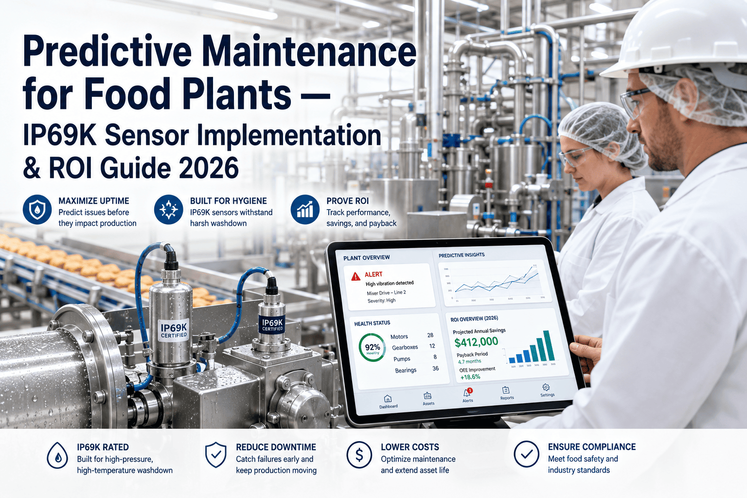
IP69K-rated vibration, temperature and current sensing, mounted where the data is true and the design stays cleanable.
Why Sensor Placement Makes or Breaks Food Plant PdM
Two things go wrong with sensors in food plants. The first is data quality: sensors mounted on the wrong surface, in the wrong orientation or with the wrong method measure the mounting rather than the machine, and the analytics learn noise. The second is hygiene and durability: sensors, brackets and cables that are hard to clean, or that cannot survive hot high-pressure washdown, either create food safety risks or fail within months.
Both problems are cheaper to prevent than to fix. A placement plan agreed with maintenance, sanitation and quality before installation avoids re-work, and it produces data the models can trust from day one. That is why every iFactory deployment starts with a site survey.
Understand What the Ratings Actually Test
IP69K is the rating most often specified for food washdown areas. It is defined in ISO 20653, and IEC 60529 includes a comparable high-pressure, high-temperature water test. According to test laboratory Applus+ Keystone, the IP69K water test uses 80–100 bar water at 80°C, sprayed from 10–15 cm for 30 seconds at each of four angles, 0°, 30°, 60° and 90°, with the sample on a turntable at 5 rpm.
| Standard or guideline | What it covers | What it means for PdM sensors |
|---|---|---|
| IP69K (ISO 20653) | Protection against high-pressure, high-temperature water jets and dust | Minimum for sensors, connectors and housings in hot high-pressure washdown zones |
| IP67 and IP68 | Temporary or continuous immersion | Useful, but not a substitute for IP69K where high-pressure hot washdown is used |
| EHEDG Guideline 37 | Hygienic design and application of sensors | Design and integration principles, including product-contact areas |
| 3-A Sanitary Standard 74 | Sensors, sensor fittings and connections on milk and milk product equipment | Applies to product-contact sensors; most PdM sensors are non-contact |
| Plant hygienic design rules | Your own zoning, materials and cleaning procedures | The final authority on what can be installed where |
Note the distinction: most condition monitoring sensors sit outside the product zone, on bearing housings, motors and cabinets. Product-contact standards apply when a sensor touches product; hygienic design principles apply everywhere. Our team can map your zones before any sensor is chosen.
Accelerometer Mounting Rules
Mounting has a large effect on what an accelerometer can measure. Vibration specialist enDAQ describes stud mounting as the best method for accelerometer performance, maximizing frequency response, and notes that with adhesive mounting the thickness of the bond line matters more than the adhesive type. Magnetic mounts are convenient on ferrous surfaces but compromise performance, and handheld probes limit the usable range to below roughly 100 Hz.
Drilling and tapping equipment may affect warranties or hygienic design, so agree the method with the equipment maker and your hygiene team. We can help plan the mounting points.
Hygienic Design Rules for Sensors, Brackets and Housings
Housings, brackets and fasteners in stainless steel, typically 316 grade near product zones, with seal materials that tolerate your cleaning chemicals.
Rounded, sloped surfaces that shed water; no gaps between sensor and bracket that trap soil.
Enough clearance around each sensor and bracket for sanitation crews to clean and inspect.
Fewer, sealed fasteners; no loose parts that could fall into product.
Engraved or durable tags that survive washdown, not paper labels or tape.
Electronics, gateways and power supplies kept outside high-care washdown areas where possible.
EHEDG’s Guideline 37 is a useful reference for these principles. Our engineers review every bracket design with your hygiene team.
Cable Routing and Connections in Washdown Areas
Wireless sensors reduce cabling but bring their own checks: battery access, housing rating, radio coverage around stainless equipment and gateway placement. Ask our team whether wired or wireless suits each area.
Temperature, Current and Process Signals
| Signal | Best placement | Common mistake | Better practice |
|---|---|---|---|
| Bearing temperature | Bearing housing near the outer race | Mounting on a cover plate | Direct contact with the housing, sealed cable |
| Seal chamber temperature | Seal gland or flush line | Measuring ambient air near the seal | Contact sensor on the gland or flush outlet |
| Valve cover temperature (compressors) | Each valve cover | One sensor per cylinder | One per valve cover to localize leaks |
| Motor current | MCC or drive cabinet | Clamp meters in the washdown area | Permanent current transformers in the cabinet |
| Pressure (process) | Existing hygienic process connections | Adding new product-contact ports | Use existing transmitters where possible |
| Speed and position | Existing encoders and drives | New sensors on moving parts | Read the drive or PLC signal |
The cheapest sensor is often the one already installed. Current, speed, pressure and temperature signals in PLCs and drives are usually available with no new hardware, which our specialists confirm during the survey.
Making Sensor Data Ready for AI
A well-placed sensor still produces weak analytics if its data lacks context. Models need to know what the machine was doing when each measurement was taken: running or stopped, which product, what speed and load, before or after a changeover or a clean. Without that context, a normal change in operating conditions looks like a fault.
Setting these up at installation avoids months of data clean-up later. We can share our data specification.
Commissioning and Validation Checklist
See how sensor health is monitored in a guided demo.
How iFactory Handles Food-Grade Sensor Deployment
Hygiene zones, washdown methods and existing signals mapped first.
Sensor, position, orientation and mounting method per asset.
IP69K-rated sensors, stainless brackets and sealed cabling.
PLC, drive and process data used before adding hardware.
Operating state, product and washdown flags attached to data.
Loose mounts, ingress and dropouts detected automatically.
Our scope covers installation, and your hygiene and maintenance teams sign off every area. Talk to our engineers about your plant.
Get a Placement Plan Your Hygiene Team Will Approve
Share your equipment list and hygiene zoning. We propose sensors, positions, mounting and cable routes that deliver clean data and pass sanitation review.
Signal noise jumped after washdown and the reading no longer tracks the non-drive end. Mount or gland needs checking.
How Deployment Works
iFactory ships as a pre-configured NVIDIA AI server, racked and ready with the condition monitoring models loaded. Rack it, plug in power and Ethernet, and the AI is live on your network. Our scope covers sensor and PLC/SCADA integration, cabling and network setup, operator and technician training, and 24×7 remote monitoring.
Server installed, sensors and controllers connected, historical work orders and failure history loaded.
Baselines learned per asset, alerts piloted on the first line with your maintenance team reviewing every finding.
Rollout to the agreed assets, technician training, CMMS hand-off and 24×7 remote monitoring in place.
Installation is scheduled around production and sanitation, area by area, with hygiene sign-off before each area goes live. The sequence is agreed on a planning call.
Frequently Asked Questions
IP69K is a protection rating defined in ISO 20653 for resistance to high-pressure, high-temperature water jets and dust. The water test uses 80–100 bar at 80°C from 10–15 cm. It is the usual minimum for hot washdown zones. Ask our engineers.
On the bearing housing, as close to the load zone as possible, on a rigid surface. Never on guards or covers. Record position and orientation so measurements stay comparable. Get a placement plan.
Stud mounting gives the best frequency response. Bonded pads work where drilling is not allowed, with thin bond lines. Magnetic mounts are best kept for temporary measurements. Our team can advise per asset.
3-A Sanitary Standard 74 applies to product-contact sensors. Most PdM sensors are non-contact, but EHEDG hygienic design principles, including Guideline 37, still guide how they are designed and installed. Talk to our specialists.
In vertical or sloped runs with stand-off clips, away from ledges and floors, using sealed connectors and glands, with drip loops before cabinets. Keep electronics outside washdown zones where possible. See our checklist.
Flag washdown and CIP periods from the PLC so the analytics ignore spray impacts and temperature shocks, and monitor sensor health so loosened mounts are caught. Ask our support team.
Sensors That Survive Washdown and Data You Can Trust
iFactory plans every sensor position, mount and cable route with your hygiene team, then monitors sensor health so the analytics always stand on solid data.
Data quality checks catch loose mounts, water ingress and cable damage before they hide a fault.