Bridge Bearing Replacement Elastomeric and Pot Bearing Methods
By Grace on June 18, 2026
A bridge bearing that seizes under thermal load does not fail quietly. The locked condition transfers forces the substructure was never designed to resist — hairline cracks in the pier cap widen, concrete spalling exposes reinforcement, and the superstructure begins to distort against its own support. Bridge owners who have managed a frozen pot bearing or a walked-out elastomeric pad know that the cost of intervention grows by orders of magnitude once the bearing failure damages the substructure. The replacement window is defined not by the bearing's rated service life, but by the gap between detectable deterioration and structural damage. This is the bridge engineer's practical guide to bearing replacement planning — from condition assessment and type selection through jacking sequence execution and AASHTO LRFD compliance verification.
Every Bearing That Fails Was Detectable at Least One Inspection Cycle Before It Became a Structural Problem. The Replacement Plan Starts With Knowing Which Stage the Bearing Is In.
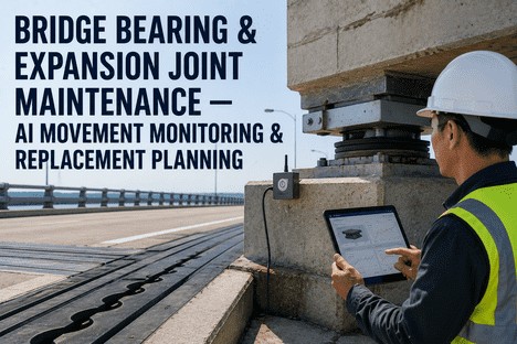
iFactory's bridge bearing replacement platform gives engineers and bridge owners a structured workflow — from field inspection data capture and condition rating through bearing type specification, jacking plan approval, and installation tolerance verification — all integrated with AASHTO LRFD Section 14 compliance requirements and bridge management system records.
of bearing deterioration discovered at Level II or earlier can be resolved through planned replacement without emergency escalation or substructure damage repair
20–30
year typical service life of laminated elastomeric bearings — with proper installation and inspection, the most cost-effective bearing solution for standard bridge applications
40–60
year service life of pot bearings with intact sealing rings and PTFE sliding surfaces — the high-load multi-rotational standard for complex geometry and heavy spans
3–5x
cost multiplier when bearing failure escalates to substructure damage — pier cap spalling, anchor bolt failure, or beam seat deterioration requiring concrete repair
Bearing Selection by Bridge Type and Load Condition: Matching the Bearing to the Structural Demand
The choice between elastomeric and pot bearing is rarely a question of preference — it is dictated by the load, movement, and rotation demands that the bearing must accommodate within the bridge's geometric constraints. AASHTO LRFD Bridge Design Specifications Section 14 and the AASHTO/NSBA G9.1 Steel Bridge Bearing Guidelines define the load ranges and movement capacities within which each bearing type is the most economical and technically appropriate solution. The table below summarises the practical selection envelope for the four bearing types most commonly encountered in bridge replacement programmes.
Bridge Bearing Type Selection Matrix — Load, Movement, Rotation, and Service Life Parameters
Bearing Type
Max Vertical Load
Rotation Capacity
Translation
Service Life
Laminated Elastomeric
Up to 700 kN (160 kips)
Low to moderate — shear deformation of elastomer layers
Up to 25 mm — accommodated by lateral shear
20–30 years
Pot (HLMR)
Exceeds 3,000 kN — standard design stress 25 MPa on elastomeric disc
0.04–0.05 radians — confined elastomeric disc behaves as fluid
Varies — PTFE sliding surface for guided or non-guided expansion
40–60 years
PTFE Sliding / Spherical
High — limited by stainless steel mating plate design
Exceeds 0.05 radians — curved sliding surface for multi-axial rotation
Unlimited within PTFE sliding surface dimensions — low friction coefficient
30–50 years with dust cover and lubrication
Lead-Rubber Seismic Isolation
High — laminated elastomer with lead core for energy dissipation
Moderate — primarily designed for lateral displacement under seismic event
Large lateral displacement — damping capability via lead core yield
50+ years
Bearing Deterioration Assessment: The Four-Level Classification That Drives Replacement Timing
Every bearing in the national bridge inventory follows a deterioration trajectory that is predictable in sequence if not in timing. The four-level condition assessment system — adapted from the DB65/T 4812-2024 specification framework and consistent with NBI condition ratings — provides bridge owners with a structured decision ladder that maps observable deterioration to a clear action timeline. A bearing at Level I is fully functional. A bearing at Level IV requires immediate traffic restriction and replacement within weeks. The replacement strategy shifts fundamentally at each boundary.
I
Functional — Routine Maintenance Only
Elastomer shows minor surface cracking. Steel components have light surface oxidation. Bearing remains in proper alignment with expected deformation for ambient temperature. No action beyond standard inspection interval and cleaning is required. The bearing is performing as designed and has no measurable degradation affecting load transfer or movement accommodation.
II
Moderate — Plan Replacement Within 12 Months
Shear deformation exceeds 50% of bearing thickness. Elastomer bulging is visible at laminate edges. Localised pitting corrosion on sole or masonry plates. Bearing has migrated slightly from original position. Condition is stable but deteriorating. Planned replacement scheduling begins now — procurement, traffic management planning, and jacking design should be initiated.
III
Critical — Replace Within 3 Months, Restrict Traffic
Pot bearing piston is contacting pot wall — sealing rings are extruding or failed. Elastomeric pad shows splitting, tearing, or laminate exposure. Anchor bolts are loose or corroded beyond 25% section loss. Bearing is functioning at reduced capacity. Immediate traffic restriction is required — typically one lane closed — with replacement scheduled within 90 days to prevent substructure damage escalation.
IV
Emergency — Bearing Locked, Substructure Damage Active
Bearing is fully seized — no translation or rotation occurring. Pier cap shows active cracking or spalling at bearing seat. Beam end is distorting — web buckling or flange bending visible at bearing stiffener location. Bearing has walked off the masonry plate edge. Bridge requires immediate closure or single-lane emergency restriction. Replacement must proceed within weeks using expedited procurement and accelerated jacking sequence.
The Jacking Sequence: Precision Requirements and Traffic Management for Bearing Replacement
Bearing replacement requires the superstructure to be raised enough to remove the existing bearing and install the new one — typically 3 to 12 mm of vertical clearance depending on bearing type and seat condition. The damage risk during jacking is not from the lift height, but from differential displacement between adjacent girders and from unintended restraint caused by the deck diaphragm continuity. The jacking sequence must be engineered to control both total lift and differential movement within tolerances that the superstructure can accommodate without distress. AASHTO LRFD and state DOT specifications converge on a common precision requirement: maximum differential displacement of 6 mm between adjacent beams and a maximum total lift of 19 mm for simultaneous jacking at a single support.
01
Traffic Management Setup
Remove live load from span being jacked. Close affected lanes. Install traffic control per approved MOT plan. Verify live load is fully removed before jacking begins.
02
Temporary Support & Jack Installation
Install cribbing and jacking frames on adequate foundation. Position jacks at designated stiffener locations. Install displacement gauges at each jacking point. Engineer certifies temporary support system.
03
Controlled Jacking With Displacement Monitoring
Raise superstructure synchronously — max 6 mm differential per AASHTO requirement. Monitor displacement gauges continuously. Block adjacent to jacks as lift progresses for fail-safe support. Hold at target height.
04
Bearing Removal and Seat Preparation
Remove existing bearing assembly. Inspect bearing seat for cracks, spalls, or deterioration. Perform concrete repair if required. Level seat with high-strength grout and allow curing to specified strength.
05
New Bearing Installation and Load Transfer
Position new bearing at ambient temperature correction. Verify alignment, level, and anchor bolt engagement. Grout bearing plate. Release jacks gradually and synchronously. Verify bearing is seated and load is transferred. Remove temporary supports.
AASHTO LRFD Bearing Selection Criteria: Five Factors That Determine the Correct Replacement Bearing
When an existing bearing reaches Level III condition and replacement is triggered, the first decision is whether the replacement should match the original bearing type or whether a different bearing type would better serve the remaining bridge life. AASHTO LRFD Section 14 and the AASHTO/NSBA G9.1 guidelines define five factors that govern the selection envelope. The bridge owner or engineer evaluates each factor against the bridge's current condition and projected service requirements — not against the original design assumptions, which may have changed due to deck overlays, widening, or increased legal load limits.
Factor 01
Vertical Load Demand and Bearing Stress
The governing factor for bearing type selection. Laminated elastomeric bearings are practical up to approximately 700 kN per bearing. Above this threshold, pot bearings or spherical bearings become necessary — their standard design compressive stress of 25 MPa on the elastomeric disc accommodates loads that would require impractically large elastomeric pads. Replacement assessments should verify the actual dead load reaction at the bearing seat, accounting for any deck overlay added since original construction.
Factor 02
Thermal Movement and Translation Demand
Elastomeric bearings accommodate translation through shear deformation of the elastomer layers. When the required longitudinal movement exceeds approximately 25 mm, the bearing thickness required to keep shear strain below the AASHTO limit of 0.5 becomes uneconomical. At this point, PTFE sliding surfaces on pot or spherical bearings are the standard solution — the low-friction PTFE-stainless steel interface allows essentially unlimited translation within the sliding surface dimensions.
Factor 03
Rotation Capacity and Multi-Axial Demands
Bridges with significant skew, curved alignment, or differential pier settlement produce multi-axial rotation demands that exceed the capacity of standard elastomeric pads. Pot bearings accommodate rotation up to 0.05 radians through deformation of the confined elastomeric disc. Spherical bearings exceed 0.05 radians through a curved PTFE-stainless steel sliding interface. If the girder end rotation from dead load plus prestress plus live load exceeds 0.02 radians, a multi-rotational bearing is typically specified.
Factor 04
Bearing Seat Geometry and Substructure Condition
The physical space available between the girder soffit and the pier cap or abutment seat often constrains bearing type choice independently of load requirements. Pot bearings require greater vertical clearance than elastomeric pads. If the existing bearing seat is deteriorated — spalled, cracked, or with exposed reinforcement — concrete repair thickness must be accounted for in the replacement bearing height. Changes in bearing type from the original installation may require pedestal modifications or welded sole plate extensions to match the new bearing footprint.
Factor 05
Seismic Performance and Isolation Requirements
In seismic zones, the bearing replacement is an opportunity to upgrade the bridge's seismic performance without structural modification. Replacing fixed steel bearings with lead-rubber isolation bearings adds damping and reduces force demand on the substructure. AASHTO LRFD Section 14 and the AASHTO Guide Specifications for Seismic Isolation Design govern the selection and design of isolation bearings. Even when seismic isolation is not adopted, the replacement bearing must meet the anchorage and restraint requirements of AASHTO LRFD Section 3.10 for the current seismic design category.
iFactory Workflow
Integrated Bearing Selection and Documentation Platform
iFactory's bearing replacement module guides the engineer through each selection factor with a structured data entry and compliance verification workflow — load input from the bridge management system, movement calculation from temperature data and span length, rotation check against the girder end slope calculation, and substructure condition documentation from inspection records. The output is a bearing specification ready for procurement, with AASHTO LRFD Section 14 compliance verification automatically documented.
We had a four-girder continuous steel bridge where the abutment pot bearings had seized — the piston had contacted the pot wall on two of the four bearings and the pier cap was showing diagonal cracking from the locked-in thermal forces. The original replacement estimate assumed matching pot bearings with an 18-week fabrication lead time. When we ran the selection factors through iFactory's platform, we found that a laminated elastomeric solution could handle the actual dead load with a redesigned pad geometry, and the lead time dropped to four weeks. The total project cost came in at 62% of the pot bearing estimate. The selection framework caught what assumption-based specification would have missed: the original pot bearings were oversized for the actual load condition.
Bridge bearing replacement is not a mechanical task — it is a structural engineering operation that begins with accurate condition assessment, proceeds through technically justified bearing type selection, and executes under displacement control tolerances that protect the superstructure from damage. The four-level deterioration classification system gives bridge owners a clear decision framework: a Level II bearing is scheduled for planned replacement within 12 months; a Level IV bearing requires emergency intervention before the substructure is permanently damaged. The cost difference between these two paths is typically a factor of three to five.
The bearing selection decision at replacement time must account for the bridge's current load condition — not the original design loads. Deck overlays, widening, and increased legal load limits may have changed the vertical reaction at the bearing seat. The AASHTO LRFD Section 14 selection factors — vertical load, thermal movement, rotation demand, substructure geometry, and seismic requirements — provide a repeatable framework that prevents type selection based on what was installed before rather than what the bridge needs now. PTFE sliding surfaces, spherical bearings, and isolation bearings expand the solution set beyond the simple elastomeric-versus-pot binary that governs most replacement specifications.
iFactory's bearing replacement workflow integrates condition assessment data capture, selection factor analysis, jacking sequence planning, and AASHTO LRFD compliance documentation into a single platform that serves both the field inspection team and the design engineer. Book a Demo to see the bearing replacement module configured for your bridge inventory parameters, or talk to an expert about a free condition assessment gap analysis for your bridge bearing replacement programme.
Frequently Asked Questions
The decision hinges on the bearing's failure mode and the available vertical clearance. Pot bearings fail most commonly due to sealing ring extrusion, which allows the elastomeric disc to escape under compression, leading to piston-to-pot-wall contact. If the failure is sealing-related and the pot cylinder wall is undamaged, the bearing can be rebuilt in place with a new elastomeric disc and sealing rings. If the pot wall is cracked or the bearing seat is damaged, replacement with a disc bearing or spherical bearing should be considered — disc bearings eliminate the sealing ring failure mode entirely by using an unconfined urethane disc, and spherical bearings use a curved sliding surface that avoids confined elastomer components altogether. The vertical clearance requirement differs: pot and disc bearings require similar clearance, while spherical bearings may require additional height. The AASHTO LRFD Section 14 requirement that HLMR bearings be designed for replacement of internal elements applies regardless of which multi-rotational type is selected. Consult the bridge design engineer to verify that the alternative bearing type fits within the available substructure envelope. Talk to an expert about comparing pot, disc, and spherical bearing options for your specific bridge.
Industry standard and AASHTO-recommended practice limits differential displacement between adjacent beams to 6 mm (1/4 in) when jacking one beam at a time. When all beams at a single support are jacked simultaneously, the maximum total lift permitted is 19 mm (3/4 in) with the same 6 mm maximum differential between adjacent beams. These limits prevent overstress of the deck diaphragm connections and cross-frames during the jacking operation. The displacement must be monitored continuously using calibrated gauges at each jacking point — dial indicators or electronic displacement transducers with 0.1 mm resolution are standard. Pressure gauges on the hydraulic jacks are supplementary but not sufficient alone, because load redistribution between adjacent jacks can occur without visible pressure change. The jacking plan must be designed and sealed by a licensed structural engineer per most state DOT requirements, and the temporary support system — cribbing or jacking frames — must be designed for dead load plus one-half live load if traffic is fully removed, or dead load plus full live load if traffic remains on adjacent lanes. Book a Demo to see iFactory's jacking plan template with displacement monitoring documentation.
Bridges can remain partially open during bearing replacement, but the span being jacked must have live load fully removed. The standard approach is lane-by-lane replacement: close one lane, jack and replace bearings on that lane's girders, lower the superstructure, reopen the lane, and repeat for the remaining lanes. Traffic is maintained on adjacent lanes but must be restricted to the non-jacked portion of the structure. The temporary support system for the jacked lane must be designed for dead load plus one-half live load when traffic is fully removed from the jacked span, or dead load plus full live load if traffic remains on adjacent portions of the same span. Night work with full bridge closure is often preferred for accelerated bearing replacement because it eliminates the live load variable and allows simultaneous jacking of all beams at a support — reducing the total replacement duration from multiple nights to a single night for smaller bridges. The traffic management plan (MOT) must be approved by the bridge owner and local traffic authority before work begins, and the bearing replacement contractor must demonstrate that the jacking and grouting operations can be completed within the closure window. Talk to an expert about developing a staged bearing replacement MOT plan for your bridge.
Pot bearing fabrication typically requires 8 to 16 weeks from order placement to delivery, depending on the complexity of the design, the availability of the elastomeric disc material, and the manufacturer's current production queue. Each pot bearing is custom-engineered to the specific load, movement, and rotation requirements shown in the contract documents — the AASHTO LRFD requirement that HLMR bearings be designed by the supplier rather than by the bridge design engineer means that the bearing design itself is part of the lead time. Laminated elastomeric pads, by contrast, are typically stock items or require only 2 to 4 weeks for fabrication because the steel laminate layers and elastomer bonding follow standardised production processes. The lead time difference has significant programme implications: a bridge owner who discovers a Level III bearing during a routine inspection can schedule elastomeric pad replacement within a month, while pot bearing replacement requires the bearing to be ordered before the replacement window is even confirmed. For emergency Level IV situations, some HLMR manufacturers maintain a limited stock of standard-size pot bearings that can be supplied within 2 to 3 weeks, but the bearing must be designed to match the available stock dimensions rather than the other way around. Book a Demo to see iFactory's bearing procurement lead time tracker integrated with the condition assessment schedule.
Bridge bearings must be positioned at a longitudinal offset from the theoretical centred position to account for the difference between the installation temperature and the bridge's design temperature range. The offset is calculated as the product of the span length from the fixed bearing to the expansion bearing, the coefficient of thermal expansion of the superstructure material (11.7 x 10^-6 per degree Celsius for steel, 10.8 x 10^-6 for concrete), and the difference between the installation temperature and the median design temperature. For example, a 40-metre steel girder span being installed at 10 degrees Celsius with a design temperature range of -18 to +49 degrees Celsius would require the expansion bearing to be set approximately 8 mm offset from centre toward the fixed bearing end. The bearing manufacturer typically provides a temperature correction chart with the bearing delivery that specifies the offset for each 5-degree increment. The offset must be verified by the field engineer at the time of installation and documented in the bearing installation record. Some state DOTs require the bearing installation to occur within a specified ambient temperature window — typically 10 to 25 degrees Celsius — to limit the correction magnitude and reduce the risk of the bearing reaching its movement limit before the design temperature extreme is experienced. Talk to an expert about iFactory's temperature correction calculator integrated with the bearing installation checklist.
The Bearing That Fails Detectably at Level II Costs a Fraction of the One Found at Level IV. Get a Free Condition Assessment Gap Analysis for Your Bearing Replacement Programme.
iFactory's bridge bearing replacement platform — from field inspection data capture and four-level condition classification through AASHTO LRFD Section 14 bearing selection, jacking sequence planning, and installation tolerance documentation — integrated with your bridge management system records.