Bridge Cathodic Protection and Rebar Corrosion Control Methods

By Grace on June 18, 2026

bridge-cathodic-protection-rebar-corrosion-control

Chloride-laden water finds its way into bridge decks through every joint, every crack, every permeable square metre of concrete. Once it reaches the rebar, the corrosion cell activates, and the reinforcing steel begins converting to rust at a rate that is measured in millimetres of section loss per year. Spalls appear. Deck patches multiply. Load ratings drop. Eventually, the question is not whether the bridge needs cathodic protection, but how many more years of service life could have been preserved if it had been installed sooner. Bridge cathodic protection is the only NACE- and AMPP-recognised method that arrests active chloride-induced corrosion in reinforced concrete rather than simply delaying its visible consequences, and the three primary methods of delivering it -- impressed current cathodic protection (ICCP), sacrificial anode cathodic protection, and conductive overlay systems -- each carry a distinct cost profile, design life, and application window that determines whether a bridge owner gets 20 years of additional service or a recurring repair obligation that never ends.

NACE SP0290 AMPP SP0216 AASHTO Compliant
Arrest Rebar Corrosion at the Electrochemical Level. Extend Bridge Life by 20+ Years.
Impressed current, sacrificial anode, and conductive overlay cathodic protection systems deployed across 40+ bridge structures. Half-cell potential mapping, embedded reference electrode monitoring, and continuous CP performance verification.

What Is Bridge Cathodic Protection and Why Is It the Only Method That Stops Active Corrosion?

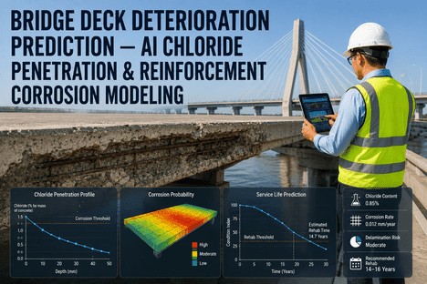
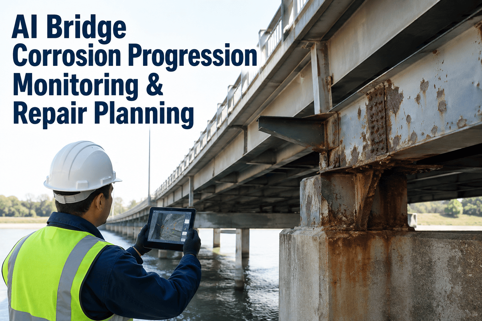
Corrosion of reinforcing steel in bridges is an electrochemical process, not a material defect. When chloride ions from de-icing salts or marine exposure penetrate the concrete cover and reach the rebar in sufficient concentration -- typically above 0.025% by weight of concrete for onset and 0.05% for active propagation per ACI 222 -- the passive oxide layer that protects the steel in the alkaline concrete environment breaks down. Anodic and cathodic sites form on the same rebar or between adjacent bars, current flows through the concrete electrolyte, and the anodic sites begin oxidising to produce expansive rust that exerts tensile stresses against the surrounding concrete. Cracking begins. Delamination follows. Spalling exposes the bar directly. This entire chain is driven by the flow of electrons from anode to cathode through the metallic path, and by the ionic current through the concrete.

Cathodic protection interrupts this chain at its source. By applying a direct current from an external anode system to the reinforcing steel, the entire rebar network is polarised into the cathodic potential range where oxidation cannot occur. The corrosion cell is not managed; it is eliminated. The CP system does not heal existing section loss, but it stops further loss and preserves the remaining steel cross-section indefinitely, provided the system remains polarised to the protection criteria defined in NACE SP0290 (impressed current) and NACE SP0216 (galvanic) for atmospherically exposed concrete structures. The 100 mV polarisation shift or the -850 mV CSE instant-off potential criteria are the verified thresholds at which corrosion rates become negligible.

20+
Years of service life extension achieved when CP is installed on chloride-contaminated bridge decks before section loss exceeds 15%.
100%
Of corrosion activity arrested at the electrochemical level when the CP system maintains the 100 mV depolarisation criterion across the protected zone.
3x
More cost-effective than deck replacement when CP is installed during the repair window between first spall appearance and widespread delamination.

The Three Bridge Cathodic Protection Methods Compared

Every bridge CP installation falls into one of three system architectures. Each delivers the same electrochemical outcome -- polarised rebar, arrested corrosion -- but the choice between them determines the capital cost, the operating complexity, the design life, and the maintenance obligation for the next two to three decades.

Method 1
Impressed Current Cathodic Protection (ICCP)

Anode types: Mixed metal oxide coated titanium mesh, ribbon, or discrete anodes embedded in a cementitious overlay or slotted into the deck surface. Transformer-rectifier supplies adjustable DC current to the anode circuit. Reference electrodes embedded in the concrete provide continuous potential feedback for automatic control.

Advantages
Adjustable current output; indefinite design life with current capacity margin; effective in high-resistivity concrete; can protect large areas from a single power source.
Limitations
Requires AC power supply and transformer-rectifier enclosure; regular monitoring and annual inspection per NACE SP0290; higher initial design and installation cost.
Method 2
Sacrificial Anode Cathodic Protection (Galvanic)

Anode types: Zinc, aluminium, or magnesium alloy anodes in discrete embedded forms, mesh panels, or thermal-sprayed zinc coatings. No external power source. The galvanic potential difference between the anode alloy and the rebar drives protective current naturally.

Advantages
No external power required; simple installation; low maintenance; ideal for targeted or localised protection of piers, abutments, and patch repairs; no stray current risk.
Limitations
Limited current output driven by anode mass; finite service life (anodes are consumed); ineffective in dry or high-resistivity concrete; cannot be adjusted after installation.
Method 3
Conductive Overlay Cathodic Protection

Anode type: Carbonaceous conductive overlay or coke-asphalt layer applied over the prepared deck surface. Functions as a distributed anode for ICCP systems. Often combined with MMO ribbon anodes embedded within the overlay for current distribution.

Advantages
Provides both corrosion protection and a new riding surface; uniform current distribution across the entire deck; proven 20-year track record on high-traffic bridges; compatible with standard paving equipment.
Limitations
Adds structural dead load; requires specialised overlay material; periodic overlay replacement needed; higher material volume per square metre than discrete anode systems.

How the Cathodic Protection System Reaches and Maintains the Protection Criteria

A cathodic protection system is only as effective as its ability to maintain the electrochemical criteria across the entire protected zone under all operating conditions. The process from installation to verified protection follows a sequence that every bridge engineer and inspector should understand.

The CP Commissioning and Verification Sequence
Step 1
Electrical continuity verification of the entire rebar network per NACE SP0290
Step 2
Baseline half-cell potential survey to map anodic zones and establish pre-CP corrosion condition
Step 3
Energisation and current ramp-up with instant-off potential readings at embedded reference electrodes
Step 4
4-hour depolarisation testing to confirm 100 mV shift criterion is satisfied at all test locations
Step 5
Ongoing remote monitoring with data-logging and annual NACE-compliant inspection reports

Half-Cell Potential Surveying: The Diagnostic That Determines the CP Strategy

Before any cathodic protection system is designed, the corrosion condition of the bridge must be mapped electrochemically. Half-cell potential surveying per ASTM C876 is the standard diagnostic method. The technique involves connecting a high-impedance voltmeter between the rebar network and a copper-copper sulphate reference electrode moved systematically across the bridge deck surface. Potential readings more negative than -350 mV CSE indicate a greater than 90% probability of active corrosion. Contour maps generated from grid-based surveys identify the precise location, extent, and severity of anodic zones. These maps define the CP zones, the current density requirement, and the anode layout long before any construction begins. Bridges surveyed before CP design consistently deliver more reliable protection at lower cost than those designed on assumed corrosion distribution.

ASTM C876 Potential Range
> -200 mV
Low corrosion probability
ASTM C876 Range
-200 to -350 mV
Intermediate corrosion probability
ASTM C876 Range
< -350 mV
High corrosion probability
Depolarisation Criterion
> 100 mV
4-hour depolarisation (NACE criterion)

Embedded Reference Electrodes: The Long-Term Monitoring Backbone

A cathodic protection system that is not monitored is a cathodic protection system that has already failed. Embedded reference electrodes are permanently installed within the concrete at representative locations across each protection zone -- typically at the most anodic locations identified by the half-cell survey, at locations with the deepest concrete cover, and at zone boundaries. Silver-silver chloride electrodes, graphite electrodes, and activated titanium electrodes are the most common types for atmospherically exposed concrete. These electrodes transmit real-time potential data to the control system, enabling automated current adjustment, alarm generation when the protection criterion is at risk, and the data archive needed for NACE-compliant annual inspection reports. Bridges with embedded reference electrode arrays from the initial CP installation maintain consistently higher compliance with protection criteria over their service life than those relying on periodic portable electrode measurements alone.

Cost-Benefit Analysis: CP Versus Deck Replacement Versus Do Nothing

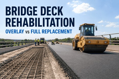
The decision to install cathodic protection is always a life-cycle cost decision, and the numbers consistently favour CP when the structure has more than 10 years of remaining functional life and the corrosion is detected before section loss exceeds 20%. A bridge deck with chloride contamination at the rebar level and active corrosion potentials has three options: do nothing until the deck requires replacement, replace the deck immediately, or install cathodic protection with targeted repairs. The do-nothing option leads to accelerating deterioration, escalating repair costs, and eventual load restriction or closure. Deck replacement costs typically run 3-5 times the installed cost of a CP system, disrupts traffic for months, and resets the service life clock but does not address the root cause of corrosion on adjacent approach spans or substructure elements. Cathodic protection stops corrosion on the existing reinforcement, preserves the structural section, and typically provides 20+ years of additional service life at 30-50% of the cost of replacement when installed during the repair window.

Life-Cycle Cost ICCP Sacrificial Conductive Overlay
The Most Expensive Correction Is the One That Has to Be Repeated Every 5 Years
Correctly designed and monitored CP systems deliver the lowest cost per year of extended service life of any bridge corrosion intervention strategy. The data is consistent across 30 years of FHWA case studies and NACE technical committee reports.

Conclusion: The Bridge Owner's Decision Window for Cathodic Protection

Bridge cathodic protection is not a speculative technology. It has been deployed on North American bridge infrastructure since the 1970s, codified in NACE SP0290, SP0216, and FHWA guide specifications, and validated by decades of polarisation data, depolarisation testing, and core sample analysis. The question facing bridge owners today is not whether CP works but whether the decision window for installing it on a given structure is still open. Once delamination exceeds 20% of the deck area, or once rebar section loss exceeds 25% in the most anodic zone, the cost of the necessary concrete repairs before CP installation can approach the cost of deck replacement. The gap between what cathodic protection can preserve and what it can recover is measured in years, and those years pass during a single biennial inspection cycle if the half-cell data is not collected and evaluated.

Every bridge that enters service today should have an embedded reference electrode array and a CP-ready electrical continuity system installed during construction -- not because the CP is needed immediately, but because the baseline condition data and the installation-ready state eliminate the 18-24 month design and procurement delay that typically follows the first corrosion-positive half-cell survey. For existing bridges, the minimum action is a half-cell potential survey at the next inspection cycle, mapped to the AASHTO element-level condition data, to identify which structures are approaching the CP decision threshold and which have already passed it. The difference between a 20-year service life extension at 30% of replacement cost and an emergency deck replacement at full cost is the half-cell survey that was or was not performed.

We had a 1968-built deck that had been patched every three years for a decade. The half-cell survey showed -420 mV CSE across 60% of the deck area. We installed an MMO mesh ICCP system with a latex-modified overlay in 2014. The system has maintained the 100 mV depolarisation criterion continuously. Ten years later, the deck has no new spalls, no new patches, and the annual monitoring reports show stable polarisation across all zones. The alternative was a full deck replacement at $2.8 million. The CP installation cost $680,000. There is no engineering argument against cathodic protection on chloride-contaminated decks. The only argument is whether you still have enough sound concrete to support the anode installation.

-- Bridge Engineer, State DOT Structure Preservation Office -- 12-Year ICCP Performance Record

iFactory provides end-to-end bridge cathodic protection services -- half-cell potential surveying, CP system design for ICCP, sacrificial anode, and conductive overlay architectures, embedded reference electrode installation, system commissioning with full depolarisation testing, and remote monitoring with NACE-compliant inspection reporting. Every installation is designed to the corrosion condition of that specific bridge, not to a template. Book a Demo to review your bridge inspection data and determine the optimal CP strategy for your structure, or talk to an expert about integrating CP-ready continuity and reference electrodes into your next new bridge or major rehabilitation project.

Frequently Asked Questions

The fundamental difference is the driving force for the protective current. Impressed current cathodic protection (ICCP) uses an external DC power source (transformer-rectifier) to drive current from durable MMO-coated titanium anodes through the concrete to the reinforcing steel. Current output is adjustable, the system can protect concrete with high electrical resistivity, and the anode system has an indefinite design life if the maximum current capacity rating is not exceeded. Sacrificial anode cathodic protection (SACP) relies on the natural galvanic potential difference between the anode alloy (zinc, aluminium, or magnesium) and the steel to generate protective current. No external power is required, but the current output is limited by the anode mass and the concrete resistivity, the anodes are consumed over time, and the system cannot be adjusted after installation. ICCP is generally preferred for large deck areas and high-chloride environments; SACP is effective for targeted protection of substructure elements, patch repairs, and zones where AC power is not available. Talk to an expert about which system matches your bridge condition and budget.

The 100 mV depolarisation criterion is the most commonly applied protection criterion for atmospherically exposed reinforced concrete structures under NACE SP0290 (ICCP) and NACE SP0216 (galvanic). The test procedure begins with the CP system operating at steady state. The instantaneous-off potential is recorded at each embedded reference electrode or at test locations using a portable reference electrode. The CP system is then switched off, and the depolarised potential is measured after 4 hours (or longer if the structure has not fully depolarised). The difference between the instant-off potential and the 4-hour depolarised potential must equal or exceed 100 mV at the most anodic location to satisfy the criterion. For ICCP systems, this test is performed during commissioning and repeated annually. For galvanic systems where the current cannot be interrupted, the 100 mV cathodic polarisation criterion from native potential is used instead. The criterion is based on the well-established relationship between a 100 mV polarisation shift and a corrosion rate reduction of approximately one order of magnitude. Book a Demo to see the commissioning protocol for your bridge type.

Yes, but the condition of the concrete determines the cost and complexity. CP installation on a bridge with existing spalling requires concrete repair to restore the section and provide sound material for anode embedment before the CP system is installed. All delaminated and spalled concrete must be removed, the exposed rebar must be cleaned and treated, and the repair areas must be reinstated with a material compatible with the CP system (typically a low-resistivity repair mortar). The repaired areas then become part of the CP zone and receive protective current along with the original concrete. The critical limitation is the extent of the repairs. If more than 20-25% of the deck area requires concrete removal and replacement, the combined cost of repairs plus CP may approach the cost of deck replacement. A half-cell potential survey combined with a chain-drag delamination survey is the standard diagnostic for determining whether the repair-to-CP cost ratio is favourable. Talk to an expert about a condition assessment and CP feasibility study for your bridge.

NACE SP0290 requires monthly remote monitoring of rectifier voltage and current output for ICCP systems, plus an annual on-site inspection that includes instant-off and depolarised potential measurements at all embedded reference electrodes and test locations, visual inspection of the rectifier enclosure and anodes, and verification that the protection criterion (typically 100 mV depolarisation) is satisfied at every test location. For sacrificial anode systems, annual potential measurements are the standard requirement, with the anode consumption rate estimated from the current output history. All monitoring data must be documented in an annual inspection report that includes the as-found potentials, the trend analysis since the previous inspection, and any corrective actions taken. Bridges with remote monitoring systems that log potential data continuously can often satisfy the monthly monitoring requirement automatically, with alarms generated when any zone deviates from the protection band. Book a Demo to discuss the monitoring and inspection plan for your CP system.

Mixed metal oxide (MMO) coated titanium anodes used in ICCP bridge systems have an essentially indefinite service life when operated within their rated current density limits. The MMO coating is electrochemically stable and does not consume at the rates typical of bridge CP operation. The rated current output for MMO mesh anodes in concrete is typically 110 mA per linear metre of ribbon at standard spacing, and the coating is designed to deliver this output continuously for 20+ years without significant degradation. The practical design life of an ICCP system is therefore determined not by the anode material but by the durability of the concrete overlay or encapsulation that protects the anode, the service life of the transformer-rectifier (typically 15-25 years), and the continued structural integrity of the bridge deck itself. When the overlay eventually requires replacement, the anode mesh can be inspected, tested, and re-encapsulated in the new overlay, effectively resetting the system service life without a full anode replacement. This indefinite service potential is the primary life-cycle cost advantage of ICCP over sacrificial anode systems, which have a finite anode mass and a predictable consumption timeline. Book a Demo to review anode system design life calculations for your structure.

Your Bridge Has a Corrosion Timeline. Cathodic Protection Rewrites It.
iFactory provides full-spectrum bridge cathodic protection services -- half-cell surveying, CP design for ICCP and galvanic systems, embedded reference electrode arrays, commissioning with depolarisation verification, and remote monitoring with NACE-compliant annual reporting. Designed to the corrosion condition of your specific structure, not a template.

Share This Story, Choose Your Platform!