A warped flange, a seam that no longer sits flat, a bolt pattern that refuses to line up at final assembly — every fabrication shop has lost hours to weld distortion, and most of that loss was preventable. Distortion is not random; it is the predictable result of uneven heat input, uncontrolled shrinkage, and restraint that was never planned in the first place. The shops that stopped fighting it did three things differently: they fixed their welding sequence, they engineered their fixturing around thermal movement instead of just holding parts still, and they started tracking every deviation digitally instead of discovering it at final inspection. If your fabrication floor is still relying on tribal knowledge and post-weld straightening, book a demo with ifactory to see how digital sequence and fixture tracking closes the gap.
Stop Discovering Distortion After the Clamps Come Off
ifactory gives welding engineers and shop floor supervisors a single digital record of sequence compliance, fixture setup, and dimensional checks — so distortion gets caught during the weld cycle, not during final QC when rework is the only option left.
Why Distortion Still Slips Past Experienced Welding Teams
Weld distortion is the cumulative result of non-uniform heat input, restraint, and shrinkage stacking up across long seams and multi-pass joints. A bead lays down intense localized heat, the surrounding cold steel resists expansion, and as the joint cools it tries to shrink back — but the restrained metal cannot return to its original shape, so it pulls, bows, or twists instead. Fixtures often hide this movement while the clamps are still engaged, which is exactly why the real damage only becomes visible once the part is released and the shop discovers a flange that no longer sits flat or a bore that has wandered off its nominal position.
The problem compounds on heavy weldments and long multi-pass structures, where small amounts of movement from individual welds add up across the assembly. One bracket twists a fraction of a degree, one panel narrows by a few tenths of a millimetre, and by the time the frame comes together for final assembly, bolt holes refuse fasteners and mating faces need to be forced into alignment. None of this is a welder skill problem. It is a sequencing, fixturing, and documentation gap — and it is entirely correctable with the right process controls in place.
Localized Heat Input
The arc deposits intense, concentrated heat into a narrow zone while the surrounding base metal stays cool, creating a steep thermal gradient across the joint.
Uneven Expansion
The heated zone tries to expand, but the cooler surrounding material restrains it, building internal stress that has nowhere to release while the weld is molten.
Restrained Shrinkage
As the weld cools, the metal contracts, but the surrounding structure resists that contraction until the restraint is finally removed or overcome.
Visible Distortion
Once clamps are released, the stored stress relieves itself through bowing, twisting, or angular pull — and the part no longer matches the drawing.
Five Sequencing Techniques That Actually Control Shrinkage
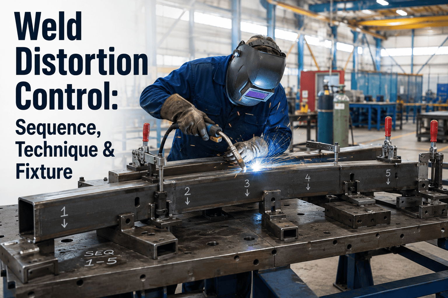
Welding sequence and direction are consistently identified as the highest-leverage control point for distortion, ahead of almost every other variable a shop can adjust. Fabrication guidance from independent welding institutes points to a small set of proven sequencing techniques, and the difference between a shop that fights distortion on every job and one that controls it reliably usually comes down to which of these five methods gets applied consistently.
Backstep Welding
Instead of running the full length of a joint in one continuous pass, the seam is broken into short segments welded in the opposite direction of overall travel. Each new segment partially offsets the shrinkage pull left by the previous one, keeping cumulative movement low across long seams.
Skip Welding
Short welds are placed at distant points along the joint rather than in sequence, giving each segment time to cool before the next one is struck nearby. This lets heat dissipate gradually instead of building up in one continuous thermal front.
Balanced or Center-Out Welding
Welding proceeds outward from the center of a panel or alternates on opposite sides of the neutral axis, so the shrinkage forces on one side cancel the pull developing on the other instead of stacking in a single direction.
Pre-Setting and Pre-Cambering
The part is intentionally positioned in the fixture with an offset opposite to the expected shrinkage direction, so that as the weld cools and pulls, it settles back into the correct final geometry rather than away from it.
Controlled Heat Input Selection
Lower heat input processes and tighter travel speed control reduce the size of the affected thermal zone, which directly reduces the volume of metal that has to shrink and therefore the total distortion generated.
Turn Sequencing Rules Into an Enforced Digital Procedure
A written welding sequence only works if every welder actually follows it on every part. ifactory turns your approved sequence into a step-by-step digital procedure with sign-off checkpoints, so deviations get flagged before the weld is made — not after the part is already warped.
Sequencing Technique Comparison: Reduction Potential and Best Fit
| Technique | Primary Mechanism | Best Fit | Typical Trade-Off |
|---|---|---|---|
| Backstep Welding | Offsets shrinkage segment by segment | Long, straight seams | Slightly slower travel planning |
| Skip Welding | Allows heat to dissipate between segments | Thin-plate panels prone to warping | Requires strict sequence discipline |
| Balanced / Center-Out | Cancels pull across the neutral axis | Wide panels and stiffened structures | Needs two-sided or team access |
| Pre-Setting | Uses anticipated shrinkage constructively | Repeatable, high-volume assemblies | Requires validated offset data |
| Low Heat Input Process | Shrinks the total affected zone | Precision or thin-wall components | Often lower deposition rate |
Fixture Design: The Other Half of Distortion Control
Sequencing controls where and when heat is applied, but the fixture decides what the part is allowed to do while that heat is being applied and removed. A well-engineered welding fixture is not a passive holding device — it is an active distortion-control system that restrains the part in its correct geometry, manages heat flow away from the joint, and gives the sequence somewhere consistent to work from. Get the fixture wrong and even a perfect sequence will not save the part.
Locate to Datum Surfaces, Not Formed Edges
Fixture locators should reference machined or datum surfaces that define the features critical to downstream assembly — bores, flanges, bolt patterns, and mating faces. Locating off a formed or cut edge invites misalignment that no amount of clamping force can correct later.
Keep Clamps Away From the Weld Zone
Clamping too close to the joint traps heat, distorts the part locally, and exposes the clamp to spatter damage. Positioning clamps back from the joint while still restraining the part around its neutral axis gives the sequence room to work as designed.
Build In Heat Sinks Where Possible
Water-cooled backing bars, copper heat sinks, and heavy strongbacks pull heat away from the joint faster than still air, reducing the size of the thermal gradient and the residual stress that follows once the joint cools.
Allow Controlled Expansion, Not Rigid Lockdown
Spring-loaded or sliding fixture elements can maintain consistent clamping pressure while still accommodating the thermal growth of the part during the weld cycle, which prevents the trapped stress that rigid over-clamping tends to create.
Validate With Trial Welds and Measurement
Initial weld trials on a new fixture should be measured for distortion, with locator shims and clamp pressure adjusted based on what actually happens on the part — not just what the fixture drawing assumed would happen.
Building the Program: From Drawing to Documented Weldment
Individually, a good sequence and a good fixture each reduce distortion. Combined into a documented, repeatable program, they turn distortion from an unpredictable variable into a managed one. The steps below reflect how fabrication teams that have solved this problem structure their process, from the drawing review stage through final dimensional sign-off.
Review the Drawing for Restraint and Weld Volume
Identify which joints carry the highest heat input and which features are critical to final function, so fixture design and sequencing effort gets focused where it matters most rather than spread evenly across every weld.
Design the Fixture Around Datums and Thermal Movement
Build locating and clamping around the datum surfaces identified in the drawing review, and plan for the part's expected thermal growth rather than assuming it will hold perfectly still under clamp pressure.
Write and Approve the Welding Sequence
Select backstep, skip, or balanced welding based on the joint geometry and stiffness, and document the exact order so every welder on every shift follows the identical approved path.
Run and Measure a Trial Weldment
Weld a first article against the documented sequence and fixture setup, then measure critical dimensions before and after clamp release to confirm the plan is actually controlling distortion as intended.
Digitize Sign-Off for Every Production Run
Once validated, the sequence and fixture setup should be logged and checked off on every subsequent part, so a deviation from the approved plan is caught at the weld station rather than discovered at final inspection.
Frequently Asked Questions on Weld Distortion Control
What is the single biggest cause of weld distortion on long seams?
Uncontrolled welding sequence is consistently identified as the highest-impact factor once fixture restraint is in place. When a long joint is welded continuously in one direction, shrinkage accumulates progressively along the seam instead of being offset segment by segment. Switching to a backstep or skip welding pattern breaks that continuous heat front and lets each segment's shrinkage partially cancel the one before it, which is why sequence changes alone often produce a measurable reduction before any fixture redesign is even needed. Teams that want a repeatable way to enforce the correct sequence on the shop floor can book a demo to see how digital sequence tracking works in practice.
Can fixturing alone eliminate distortion without changing the welding sequence?
Fixturing significantly reduces visible movement while the part is clamped, but it does not eliminate the underlying stress — it converts some of the expected distortion into residual stress trapped inside the part instead. That stress can still show up later as warping once the part is released, machined, or stress relieved, which is why fixturing and sequencing are always described as complementary controls rather than substitutes for each other. A rigid fixture combined with a poor sequence still produces a stressed, unpredictable weldment even if it looks dimensionally correct the moment the clamps come off.
How do we decide between backstep, skip, and balanced welding for a specific part?
The choice generally follows joint geometry and access. Long, straight, single-sided seams typically respond best to backstep welding because it directly counters the progressive pull of continuous travel. Thin panels prone to buckling benefit more from skip welding, which spreads heat input out in time and space. Wide, stiffened panels or double-sided joints usually respond best to balanced or center-out welding, since access to both sides lets shrinkage forces cancel across the neutral axis rather than stacking in one direction. Documenting the selected technique per joint type, rather than leaving it to individual welder judgment, is what makes the choice repeatable across shifts.
What role does heat input control play alongside sequence and fixturing?
Heat input sets the size of the affected thermal zone, and a smaller thermal zone means less metal has to expand and contract, which directly reduces the total distortion generated regardless of how good the sequence or fixture is. Lower heat input processes, tighter travel speed control, and reduced weld volume through better joint design all shrink that zone. This is why distortion control programs typically address heat input, sequence, and fixturing together rather than treating any single lever as sufficient on its own — each one reduces a different piece of the total movement.
How can we tell if our current distortion problem is a fixture issue or a sequence issue?
Measuring the part at multiple stages — after fit-up, mid-sequence, and after clamp release — usually isolates the cause. If the part is holding its shape while clamped but distorts significantly once released, the fixture is likely masking a sequencing problem that only shows up as residual stress. If the part is visibly moving even while still under restraint, the fixture itself is under-designed for the thermal load. Structured measurement at each stage, logged against the approved procedure, removes the guesswork. Teams that want help setting up that kind of measurement and documentation workflow can contact support to walk through their current process.
Make Distortion Control a Documented Process, Not a Guessing Game
ifactory connects your approved welding sequence, fixture setup checklist, and dimensional sign-off into one digital record, so every welder follows the same validated procedure and every deviation gets caught before the part is scrapped or reworked.