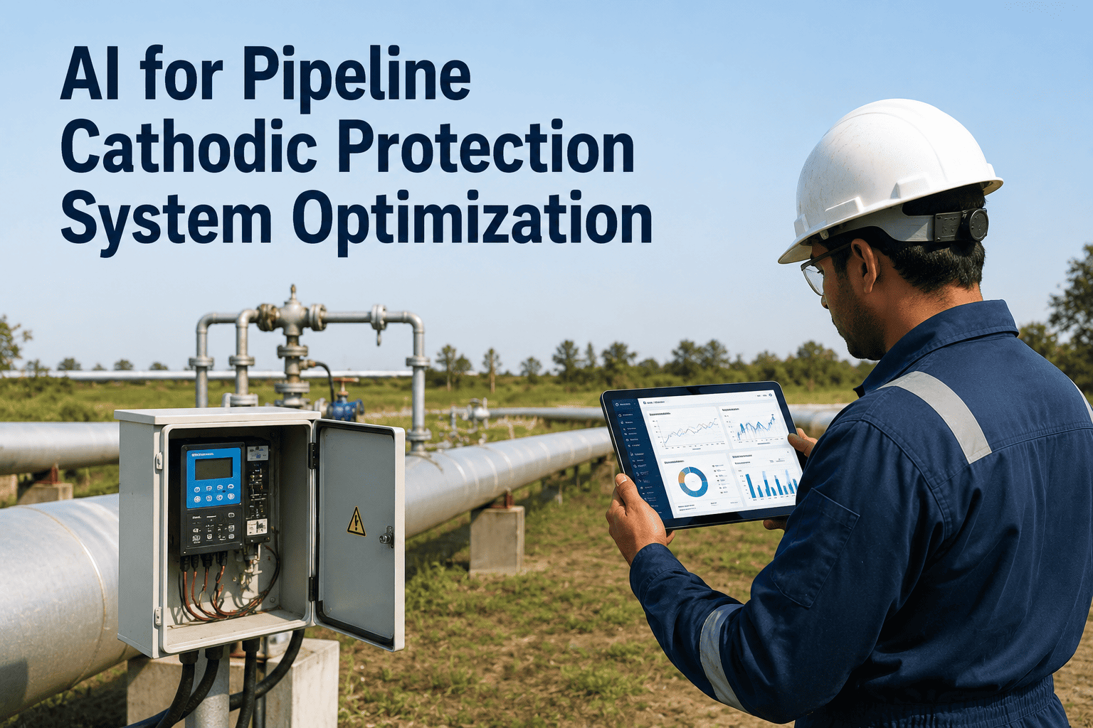
Cathodic protection is the one line item on a pipeline integrity budget that is supposed to work quietly in the background for decades without anyone thinking about it, and that is exactly why it fails so often in ways nobody notices until an inline inspection tool finds external corrosion nobody expected. A CP system that was designed correctly on paper in year one can drift out of protection by year eight because a nearby foreign pipeline was installed, a rectifier tap setting was never revisited, or a test station was paved over and stopped getting read. Getting the design right the first time, and then actually monitoring pipe-to-soil potential on a schedule instead of an audit trail, is what separates operators who catch a coating holiday before it becomes a leak from operators who find out from a third-party excavation crew. Book a roadmap call to see how AI-assisted CP monitoring closes that gap for buried pipeline systems.
Cathodic Protection Design and Monitoring That Actually Holds Up Over Decades
Impressed current and galvanic anode system design, NACE protection criteria, rectifier and anode bed sizing, and remote monitoring that flags a failing system months before the next scheduled survey.
Why Cathodic Protection Still Fails on Well-Designed Pipelines
Most CP-related external corrosion failures are not design failures at all. They are monitoring failures on systems that were sized correctly the day they were commissioned and never checked closely again.
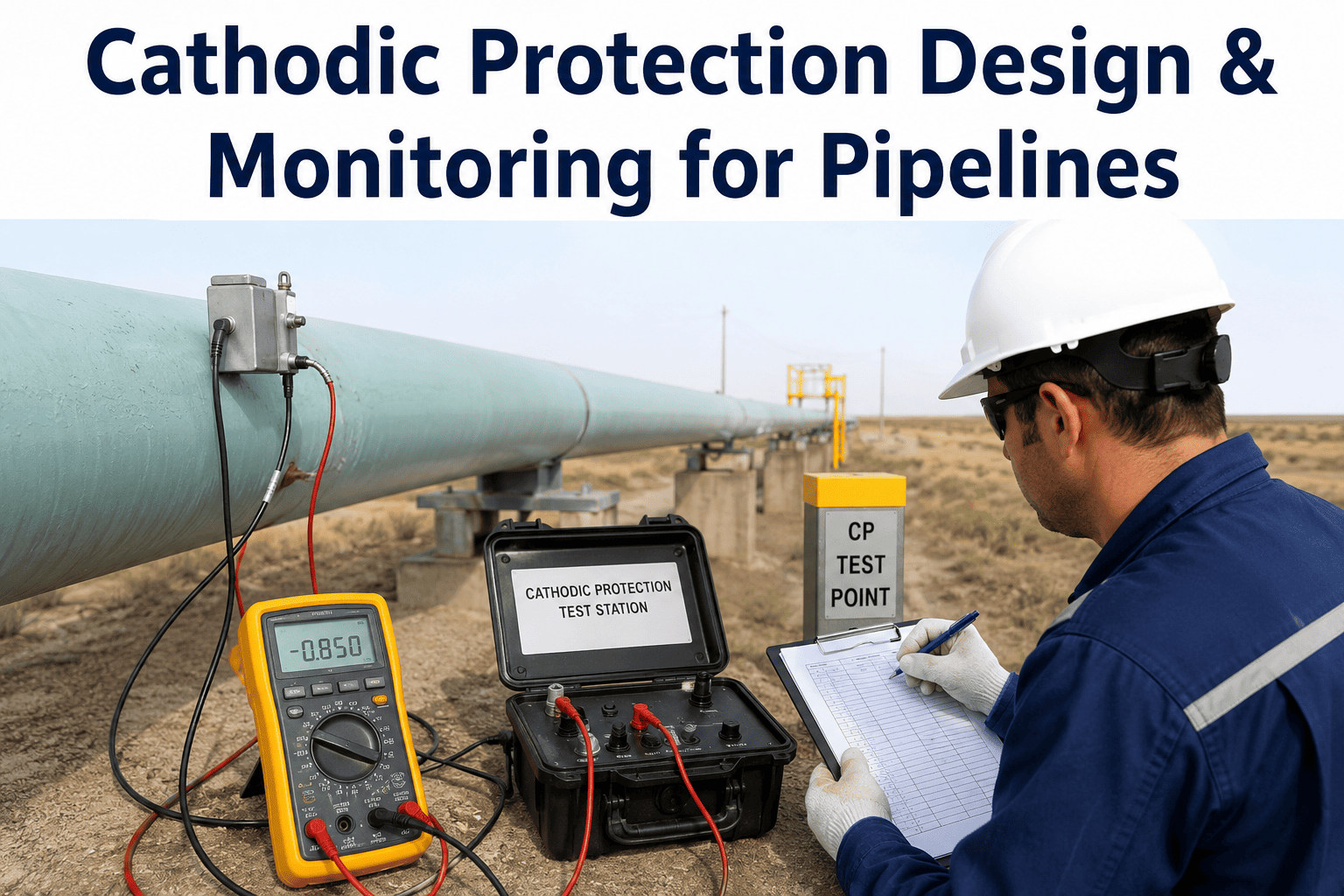
the classic NACE polarized potential criterion most pipeline CP systems are still designed and audited against
minimum depolarization shift used as an alternative criterion where native potentials vary across a route
typical design life expected from a correctly sized impressed current system with periodic anode bed rehabilitation
common minimum interval between rectifier readings under most regulatory inspection schedules, often the only reading taken
Impressed Current vs. Galvanic Anode Systems
The choice between the two approaches is rarely about which technology is superior. It is about soil resistivity, pipeline length, coating quality, and how much ongoing power infrastructure the route can realistically support, and a hybrid approach combining both is common on longer routes with varying soil conditions along their length.
Impressed Current CP (ICCP)
Uses a rectifier to drive DC current from an external power source through inert or semi-inert anodes, typically high-silicon cast iron or mixed metal oxide. Well suited to long transmission pipelines, high-resistivity soils, and routes where a single well-placed anode bed can protect many miles of pipe from one location.
The tradeoff is a dependency on grid power or solar supply, a rectifier that needs periodic tap adjustment as the coating ages and current demand rises, and a real risk of interference on any foreign metallic structure sharing the same corridor.
Galvanic (Sacrificial) Anode CP
Relies on the natural potential difference between the pipe steel and a more active metal, usually magnesium in low-resistivity or neutral soils and zinc in marine or very low-resistivity environments. No external power supply, no rectifier to maintain, and essentially no interference risk on nearby structures.
The output current per anode is small, which makes galvanic systems a poor fit for long high-resistivity routes or for well-coated pipe that briefly loses coating integrity over a large surface area. Anode consumption and replacement cycles also need to be tracked over the design life.
NACE Protection Criteria Used to Confirm Adequate Protection
A CP system can be energized and still leave sections of pipe unprotected. Confirming adequate protection means checking measured potentials against one of a small set of recognized criteria, not just verifying that the rectifier is switched on.
Rectifier and Anode Bed Sizing Fundamentals
Undersizing a rectifier or anode bed at the design stage is the single most common reason an impressed current system stops delivering adequate protection years before its rated life, usually as coating condition degrades and current demand climbs. A design that only accounts for day-one coating conditions leaves no margin for the pipe to age, which is exactly when the system needs the most reserve capacity available.
Current demand estimate
Based on coating conductance, pipe surface area, and an assumed coating breakdown factor that increases over the design life, not the coating condition on day one.
Anode bed resistance
Calculated from soil resistivity, anode configuration, spacing, and backfill type, since resistance to earth determines how much rectifier voltage is actually needed.
Rectifier voltage and amperage
Sized with headroom above the calculated demand so the unit can be turned up over its life instead of being replaced when the original design margin runs out.
Anode life and consumption rate
Matched to the design life so the anode bed does not need replacement mid-life, since anode bed excavation is one of the more disruptive maintenance events a CP system requires.
CP Survey Methods Used to Confirm Coverage Along the Route
Point-by-point test station readings confirm protection at fixed locations, but they say nothing about the pipe in between. Close interval and coating condition surveys fill that gap, and each one answers a slightly different question about the health of the system rather than duplicating the same check.
Test station readings
Fixed-interval pipe-to-soil potential readings at accessible test stations, the baseline monitoring method every regulated pipeline already performs on a set schedule.
Close interval survey (CIS)
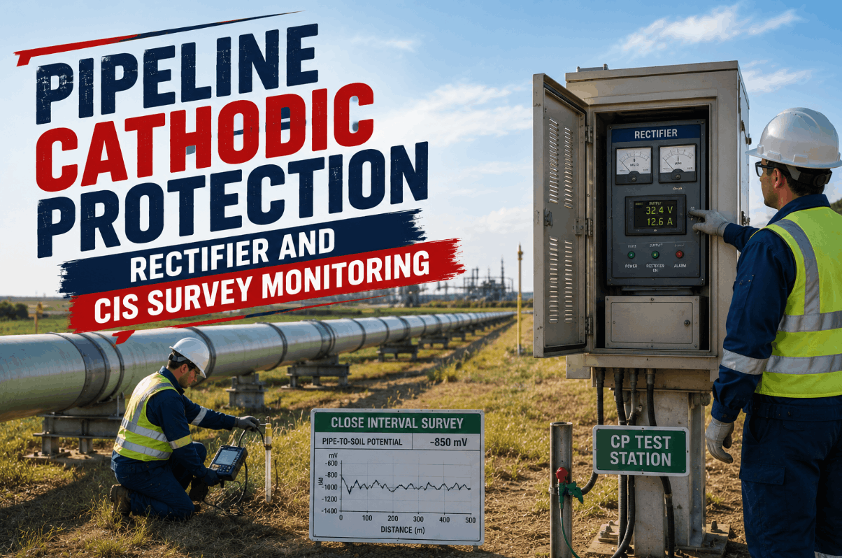
Potential readings taken every few feet along the entire route, walking the line with a reference cell to identify localized areas of inadequate protection between test stations.
DCVG coating survey
Direct current voltage gradient surveying that locates individual coating holidays and ranks their severity, guiding which sections justify excavation and recoating.
Interference and stray current testing
Checks for the influence of nearby CP systems, HVDC transmission, or DC transit systems that can drive current onto or off of the pipeline in ways the design never anticipated.
Interference and Shielding Problems That Undermine a Correct Design
A CP system can be designed and installed correctly and still leave the pipe unprotected because of a condition that developed years later, often from activity that had nothing to do with the pipeline operator. New construction along a shared right-of-way, a neighboring facility upgrading its own CP system, or simple coating aging can all quietly undo years of correct protection without any single event flagging that something changed.
Foreign structure interference
A newly installed CP system on a crossing pipeline, casing, or grounding grid can pick up stray current from a neighboring system, creating accelerated corrosion at the pickup and discharge points on both structures.
Disbonded coating shielding
Disbonded coating that stays electrically continuous with the pipe can shield the underlying steel from CP current entirely, so the pipe reads as protected at the surface while corrosion continues underneath the disbondment.
Casing shorts at road and rail crossings
A metallic short between a carrier pipe and its casing at a crossing can drain CP current away from the carrier pipe entirely, leaving that section effectively unprotected regardless of rectifier output elsewhere on the line.
AC induction from parallel power lines
Pipelines routed near high-voltage AC transmission corridors can pick up induced AC voltage that complicates potential readings and, at sufficient current density, causes its own corrosion mechanism independent of DC protection levels.
Get a CP System Design Reviewed Against Your Actual Soil Data
iFactory can walk through your resistivity survey, coating condition, and route length to confirm whether impressed current, galvanic, or a hybrid approach fits your pipeline.
Remote Monitoring Turns Six-Month Readings Into Continuous Coverage
The regulatory minimum reading interval was never meant to be the actual monitoring strategy. It was set as a floor for a manual process, and most rectifier failures and interference events happen and get corrected between those scheduled readings without anyone finding out until the next one.
rectifier output and reference cell readings from remote monitoring units instead of a semiannual manual visit
typical alert time after a rectifier trips or an anode bed fails, versus discovering it at the next scheduled check
of monitored test stations covered continuously instead of the sampled subset a field crew can physically reach in a survey window
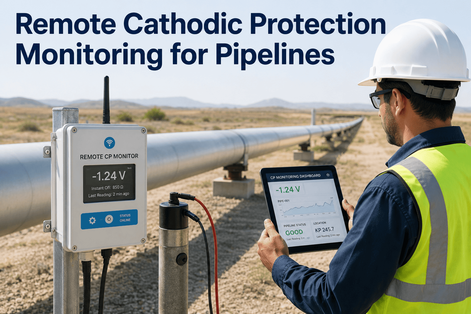
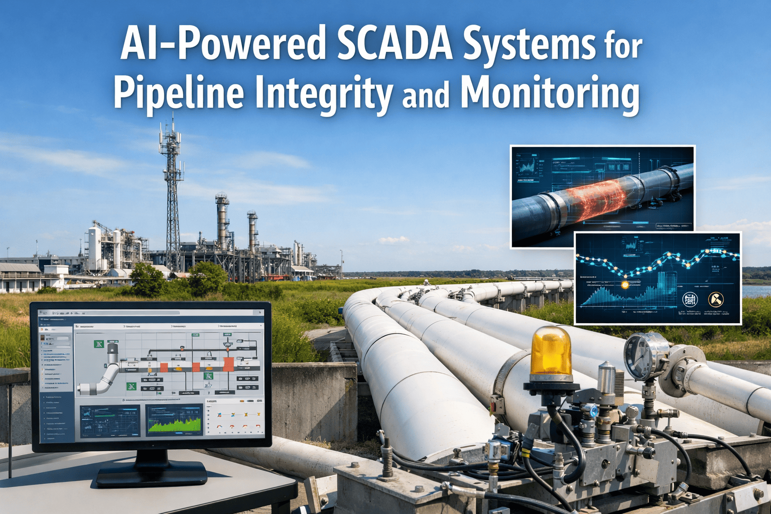
Remote units transmit rectifier output current and voltage, structure-to-electrolyte potential, and interference readings back to a central platform that flags deviations against the design baseline, so a drifting tap setting or a failing anode bed shows up as a trend line months before it would surface on the standard reading schedule. Solar-powered units make this practical even at remote right-of-way locations with no grid power nearby, and cellular or satellite backhaul means a reading interruption itself becomes a signal worth investigating rather than a gap that simply gets filled in retroactively at the next site visit.
What a Missed CP Failure Actually Costs Compared to Catching It Early
The economics of CP monitoring are lopsided in a way that rarely gets stated plainly: the entire cost of a remote monitoring rollout across a pipeline system is usually smaller than the cost of a single unplanned excavation and repair caused by a CP system that failed quietly between scheduled readings. The comparison below is not a hypothetical; it is the same failure mode playing out on two different timelines, one where the deviation is caught early and one where it is caught late.
Rectifier failure caught within days
A tripped rectifier or blown fuse identified through remote monitoring is typically a same-week service call, since the affected segment has only been unprotected for a short window and no accelerated corrosion has had time to develop.
Rectifier failure caught at the next scheduled reading
The same failure discovered at a routine six-month reading means months of unprotected pipe in soil conditions the design never accounted for going unprotected, followed by a close interval survey to find out how much damage occurred before any repair scope can even be defined.
Interference caught through trending
A new foreign structure interference source identified through continuous potential trending can be bonded and corrected before either structure sees measurable metal loss, usually a modest engineering and field cost.
Interference discovered through a leak
The same interference condition discovered through a third-party leak report or inline inspection finding means emergency excavation, regulatory notification, and a repair scope that was entirely avoidable had the trend line been visible six or twelve months earlier.
Where AI-Assisted Analysis Adds to Standard CP Monitoring
Remote monitoring solves the data collection problem. It generates far more readings than a manual program ever could, which creates a second problem: someone still has to notice when a reading trend matters before it becomes a failure, and a human reviewer scanning thousands of daily readings across a multi-mile pipeline system is exactly the kind of pattern-recognition task that gets missed under normal workload.
Baseline deviation detection
Every rectifier and test station reading is compared continuously against its own historical baseline rather than a single fixed threshold, so a gradual current demand increase gets flagged as a trend long before it crosses a pass/fail line.
Cross-correlation across nearby structures
Potential shifts at test stations near a newly energized foreign CP system get correlated automatically, surfacing an interference source that would otherwise require an engineer to notice two unrelated data points moving together.
Automatic work order generation
A flagged deviation routes directly into the CMMS as a pre-scoped work order with the relevant reading history attached, rather than sitting in a report a field crew may not review for weeks.
Prioritized survey scheduling
Segments showing the earliest signs of drift get prioritized for the next close interval or DCVG survey window, instead of every segment being surveyed on the same fixed interval regardless of actual condition.
Design Records That Need to Survive Staff Turnover
A CP system is only as good as the paper trail behind it. Original design calculations, as-built anode bed locations, and the reasoning behind a specific rectifier tap setting routinely walk out the door with the engineer who set them up, leaving the next person to guess at why a system is configured the way it is. Pipeline operations teams turn over far faster than a CP system's design life, which means the documentation has to outlast several generations of staff to remain useful at all.
Original design basis
Soil resistivity survey results, current demand calculations, and the assumed coating breakdown factor used to size the system, kept alongside the as-installed anode bed configuration rather than only the summary design report.
As-built test station locations
GPS-referenced test station and anode bed locations tied to the pipeline geographic information system, so a station buried under later construction or paving can still be located and re-exposed rather than quietly dropped from the reading program.
Historical reading trend, not just pass/fail logs
Full time-series rectifier and potential readings retained in a queryable format, since a single point-in-time pass/fail reading loses the gradual drift pattern that is usually the earliest and most useful warning sign available.
Change history for tap settings and repairs
A record of every rectifier tap adjustment, anode bed rehabilitation, and interference bond installed since commissioning, with the reasoning behind each change, so a new engineer inheriting the system is not left reverse-engineering decisions from a decade earlier.
CP Program Health Checklist
Every rectifier reading logged and trended against its original design output, not just checked against a pass/fail threshold
Close interval survey completed within the last CP evaluation cycle for high-consequence route segments
Casing shorts tested at every road and rail crossing, not assumed absent since the original installation
Interference bonds verified at every location where a foreign structure crosses or parallels the pipeline right-of-way
Anode bed and rectifier remaining life reassessed against actual current output trend rather than the original design assumption
Test station accessibility confirmed, since a buried or paved-over test station stops getting read long before anyone notices it is missing
Frequently Asked Questions
How do I know whether a pipeline route needs impressed current or galvanic anodes?
The decision comes down largely to soil resistivity and route length. High-resistivity soils and long transmission routes generally favor impressed current, since a single anode bed and rectifier can protect a long section economically. Low-resistivity or marine environments, short pipeline segments, and situations where interference risk on nearby structures needs to be avoided altogether tend to favor galvanic anodes. Book a demo to walk through the tradeoffs against your own resistivity survey data.
What causes a CP system that passed commissioning tests to lose protection later?
The most common causes are coating degradation that increases current demand beyond the original design margin, a newly installed foreign structure introducing interference, a casing short developing at a crossing, or a rectifier tap setting that was never revisited as conditions changed. None of these show up unless someone is actively trending readings against the original design rather than simply confirming the rectifier is switched on.
How often should a close interval survey actually be performed?
Regulatory minimums vary by jurisdiction and pipeline classification, but high-consequence segments generally warrant a close interval survey more frequently than the regulatory floor, particularly in areas with known interference sources, aging coating, or a history of localized failures. Remote monitoring data can help prioritize which segments need a close interval survey sooner rather than treating the whole route on a single fixed interval.
Can remote monitoring replace physical CP surveys entirely?
No. Remote monitoring covers fixed points, typically rectifiers and instrumented test stations, continuously instead of on a semiannual schedule, which catches equipment failures and interference events far faster. It does not replace a close interval or DCVG survey, which physically walks the route to find localized coating holidays between the fixed monitoring points. The two approaches are complementary rather than substitutes for each other.
How does iFactory integrate with existing CP monitoring hardware?
Integration is designed to work with common remote monitoring unit protocols already deployed on rectifiers and test stations, pulling readings into a central platform without requiring a hardware swap across an entire pipeline system. Talk to a specialist about connecting your current monitoring hardware rather than replacing it.
Design It Right and Monitor It Continuously
Book a 30-minute scoping call and bring your resistivity survey and current CP records. iFactory will show you where the design margin has eroded and what continuous monitoring would catch first.