Underground storage tanks don't announce their failures. A steel UST corroding three feet below a fuel island gives no visible warning until product reaches groundwater, a vapor monitor alarms, or a tank tightness test fails outright — and by then the cleanup bill is already running. Corrosion remains one of the most common root causes of UST releases, which is exactly why EPA's 40 CFR Part 280 regulations make cathodic protection a mandatory engineering control for bare and poorly coated steel tanks and piping. The harder problem isn't installing the system — it's proving, year after year, that the rectifier is still putting out current, the anode bed hasn't depleted, and the structure-to-soil potential still meets the protection criterion. Facilities that Book a Demo of iFactory's cathodic protection monitoring module are replacing paper rectifier logbooks with a connected record that's audit-ready on any day an inspector walks in.
Rectifier Readings, CP Surveys & Anode Life — One Connected Dashboard
iFactory AI digitizes 60-day rectifier inspections, 3-year CP surveys, and structure-to-soil potential records into a single 40 CFR 280.31-aligned compliance dashboard, so a missed reading never quietly becomes a missed deadline.
Why Underground Tanks Corrode in Silence
Steel buried in soil is already an electrochemical cell waiting to happen. Differences in soil chemistry, moisture, and oxygen concentration along a tank shell or pipe run create anodic and cathodic zones on the same structure, and current flows from the anodic areas as the metal slowly dissolves. Cathodic protection interrupts that process by forcing the entire structure to behave as a cathode, either through a sacrificial anode that corrodes in the tank's place or through a rectifier that drives protective current from an external anode bed.
Both approaches work, but they fail differently. A galvanic anode simply runs out — there's no light or meter to warn you, only a structure-to-soil survey. An impressed current system can fail in minutes if a fuse blows or a lead is severed, yet the rectifier's voltmeter only confirms power is present, not that the output is sufficient. Knowing which system protects which tank, and what each one needs monitored, is the starting point for a defensible program.
| CP System Type | Power Source | Typical UST Application | Required Monitoring | Service Life Consideration |
|---|---|---|---|---|
| Galvanic (Sacrificial Anode) | None — magnesium or zinc anode | Coated steel tanks, short piping runs | 3-year structure-to-soil survey | Anode is consumed over time; no real-time readout |
| Impressed Current (ICCP) | Rectifier (AC-to-DC) | Bare or poorly coated steel, large tank fields, high-resistivity soil | 60-day rectifier check + 3-year survey | Output is adjustable; anode bed and rectifier need periodic service |
| Supplemental Anode Addition | Combination | STI-P3 tanks needing added protection (per STI R972) | Same monitoring as the governing system type | Extends coverage where original anodes are insufficient |
| Test Station Network | Measurement only — no power source | Every CP-protected tank and pipe run | Pipe-to-soil potential reading at each station | Reference electrode condition affects reading accuracy |
Rectifier Output Monitoring: Closing the 60-Day Compliance Window
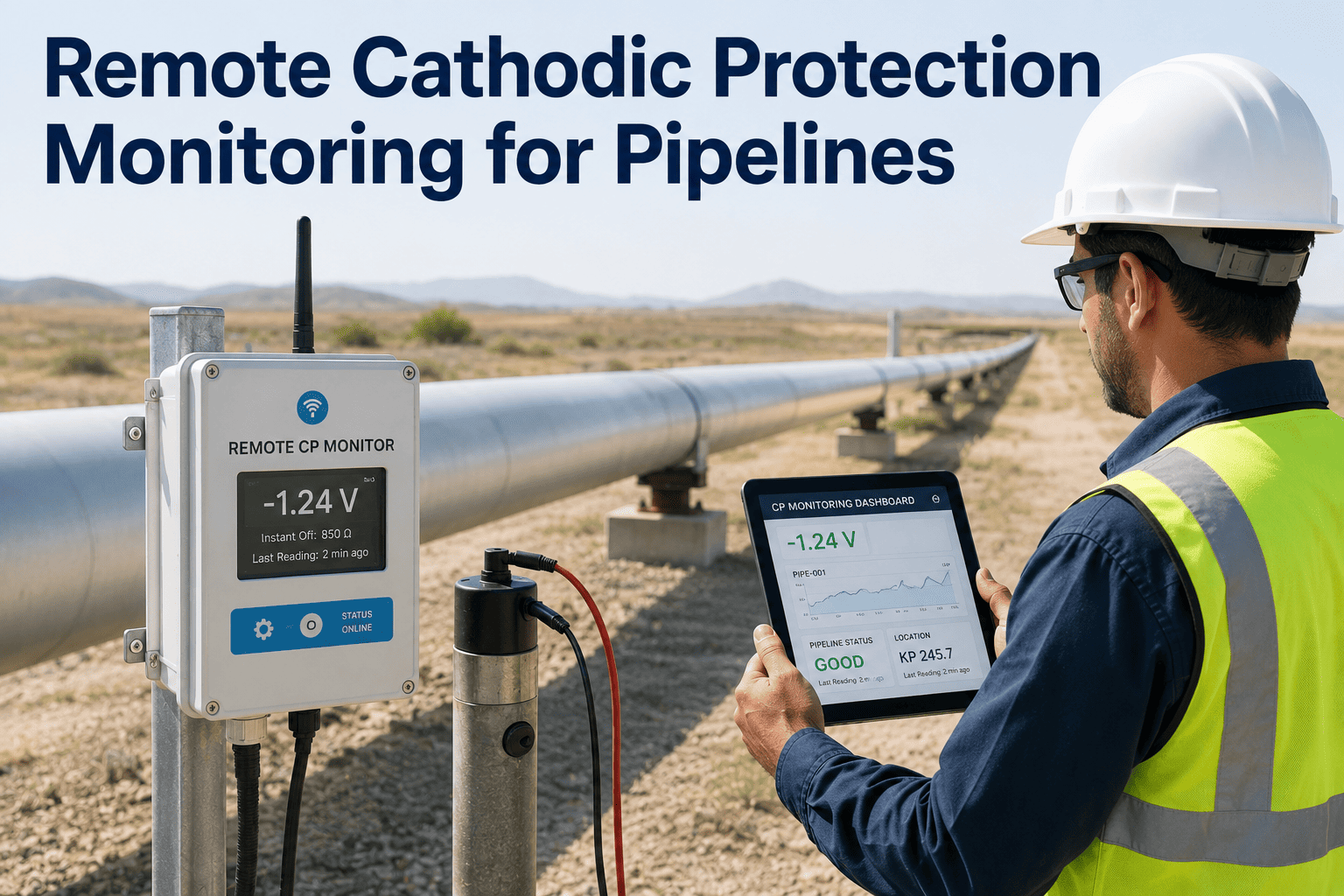
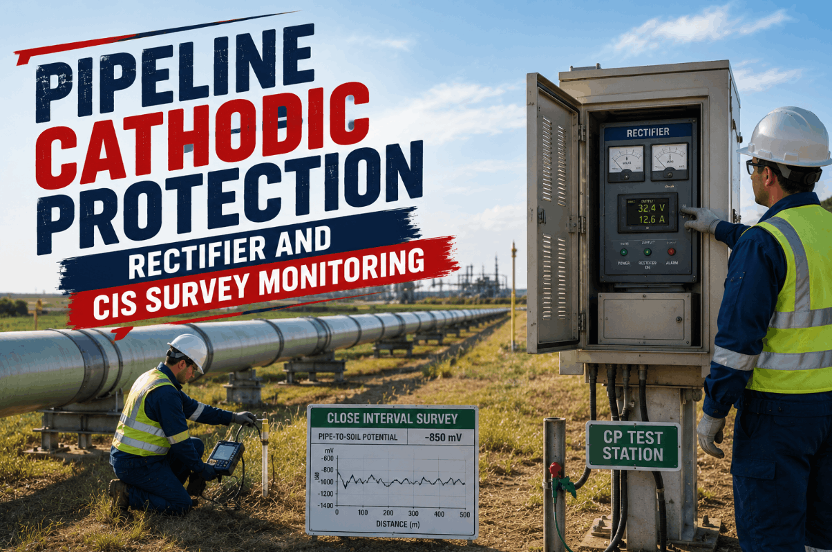
A rectifier's indicator light only confirms that power is reaching the unit — it cannot confirm the output is sufficient to protect the tank. That distinction is the reason 40 CFR 280.31(c) requires impressed current systems to be inspected at least every 60 days, with the DC voltage, DC amperage, and elapsed-time meter reading logged at each visit. In a paper logbook, a missed entry is easy to overlook for months. In a connected system, a missed or out-of-range reading is the trigger for an immediate alert rather than a surprise during the next 3-year survey. Book a Demo to see how rectifier data flows from the field to a compliance-ready log automatically.
Anode Systems, Reference Electrodes & the Survey Cycle
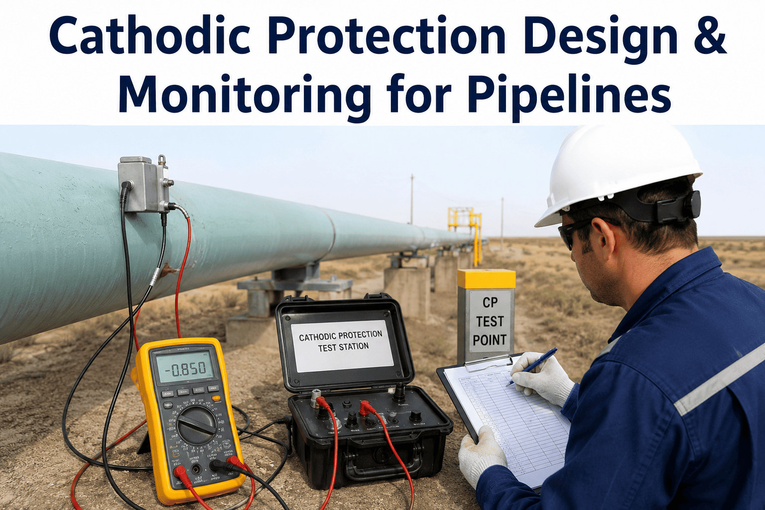
A working cathodic protection system is really four components reporting to one record: the anode delivering current, the reference electrode measuring how well it's working, the rectifier driving that current (on impressed current systems), and the test station where a qualified tester takes the reading. Treating these as one continuous data set — rather than four separate maintenance tickets — is what makes a CP program defensible rather than just documented.
Sacrificial Anodes
Magnesium or zinc anodes corrode in place of the tank, with no external power required. Anode life is finite and must be estimated from current output history rather than read off a meter.
Reference Electrodes
A copper/copper-sulfate reference electrode at each test station gives the structure-to-soil potential reading used to evaluate whether protection meets NACE SP0169 criteria.
Rectifier & Anode Bed
The rectifier converts AC power to low-voltage DC and drives current through an inert anode bed. Most single-site UST rectifiers run 5–20 amps at 10–50 volts in a NEMA-rated cabinet.
Test Stations
Fixed points where a qualified cathodic protection tester records pipe-to-soil potential for the tank and every connected piping run, not just the tank shell alone.
Owners and operators of impressed current systems can perform these inspections themselves — no certified tester required for the 60-day check, only for the 3-year survey. iFactory standardizes the reading so the same baseline range applies every time, regardless of who walks the route.
- Mobile entry for DC volts, DC amps, and elapsed-time meter readings
- Automatic comparison against the corrosion expert's documented operating range
- Photo capture of the rectifier cabinet and indicator lights at each visit
- Rolling retention of the last three readings per 40 CFR 280.31(d)
- Overdue-reading reminders sent before the 60-day window closes
The 3-year survey applies to every CP-protected UST system, sacrificial anode or impressed current alike, and must be performed by a qualified cathodic protection tester following a recognized code of practice such as NACE SP0169 or API RP 1632.
- Survey scheduling tied to each tank's last test date, not a single site-wide date
- -850 mV instant-off and 100 mV polarization criteria recorded per reading
- Digital storage of the certified tester's report and credentials
- Automatic flag if a structure fails the protection criterion
- Retention of the last two survey reports as required by 40 CFR 280.34
Galvanic systems have no meter to warn of depletion, so anode life has to be modeled from current output, anode weight, and consumption rate rather than observed directly between surveys.
- Remaining-life estimate based on installed anode weight and measured current draw
- Flags anode groups approaching end-of-life ahead of the next 3-year survey
- Cross-reference against soil resistivity data where available
- Replacement scheduling tied to estimated depletion date, not a fixed calendar
- History retained across anode replacement cycles for the life of the UST system
The most useful signal in a CP program is the slow drift that precedes a failed survey: a rectifier output trending downward over several readings, well before it drops to zero. iFactory's correlation engine surfaces that trend instead of waiting for the next 3-year test to fail.
- Time-series tracking of rectifier output across every 60-day reading
- Early-warning flag when output trends downward across consecutive readings
- Cross-correlation with prior survey results to predict which structures are at risk
- Stray current interference flagging near other buried metallic structures
- Site-wide compliance heat map showing every tank's days-to-next-deadline
The 40 CFR 280.31 Compliance Timeline
Every cathodic protection deadline in the federal UST rule traces back to one of two events: installation or repair. Knowing which clock is running for which tank — and which tanks are exempt from the 60-day cycle because they're galvanic, not impressed current — is where most facilities lose track of their own program.
Installation Baseline Test Within 6 Months
Every new CP system, galvanic or impressed current, must be tested within 6 months of installation to establish the baseline structure-to-soil potential record for that tank and its piping.
Ongoing Rectifier Checks — Impressed Current Only
Impressed current systems require a rectifier inspection at least every 60 days. Sacrificial anode systems have no equivalent component to check and move straight to the 3-year survey cycle.
Full Structure-to-Soil Potential Survey
A qualified cathodic protection tester must evaluate every CP system at least every 3 years, applying the protection criteria from a recognized code of practice to each tank and piping run individually.
Mandatory Retest After Any Repair
Any repair to a cathodically protected tank or piping system resets the clock: the CP system must be retested within 6 months of the repair to confirm it's still operating properly.
Logbooks vs. Connected Monitoring: Where Compliance Actually Breaks
Most CP compliance failures aren't caused by a corrosion expert making a bad call — they're caused by a rectifier logbook sitting in a back office while the person who knows the last reading date has moved on. A connected record doesn't change what the regulation requires; it just makes sure the requirement is impossible to lose track of.
Replace the Rectifier Logbook with a Live Compliance Record
iFactory connects rectifier readings, 3-year surveys, anode life tracking, and repair retests into one dashboard built around your actual 40 CFR 280.31 deadlines, tank by tank.
CP Compliance Is a Recordkeeping Problem Wearing a Corrosion Engineering Costume
The science behind cathodic protection hasn't changed in decades, and the federal rule that governs it is short and specific: test within 6 months of installation or repair, check impressed current rectifiers every 60 days, survey every CP system at least every 3 years, and keep the records to prove it. Almost every UST cathodic protection citation traces back to one of those four deadlines slipping through a gap in a manual process, not to a system that was actually failing to protect the tank.
iFactory's cathodic protection monitoring module treats every rectifier reading, survey, and repair retest as part of one continuous record per tank, so the deadline that matters is always visible before it's missed — not discovered during an inspection or, worse, after a release.
UST Cathodic Protection Monitoring — Frequently Asked Questions
Build a Defensible Cathodic Protection Program with iFactory AI
iFactory connects every cathodic protection data point in your UST fleet — rectifier readings, structure-to-soil surveys, anode life, and repair retests — into one record built around 40 CFR 280.31.