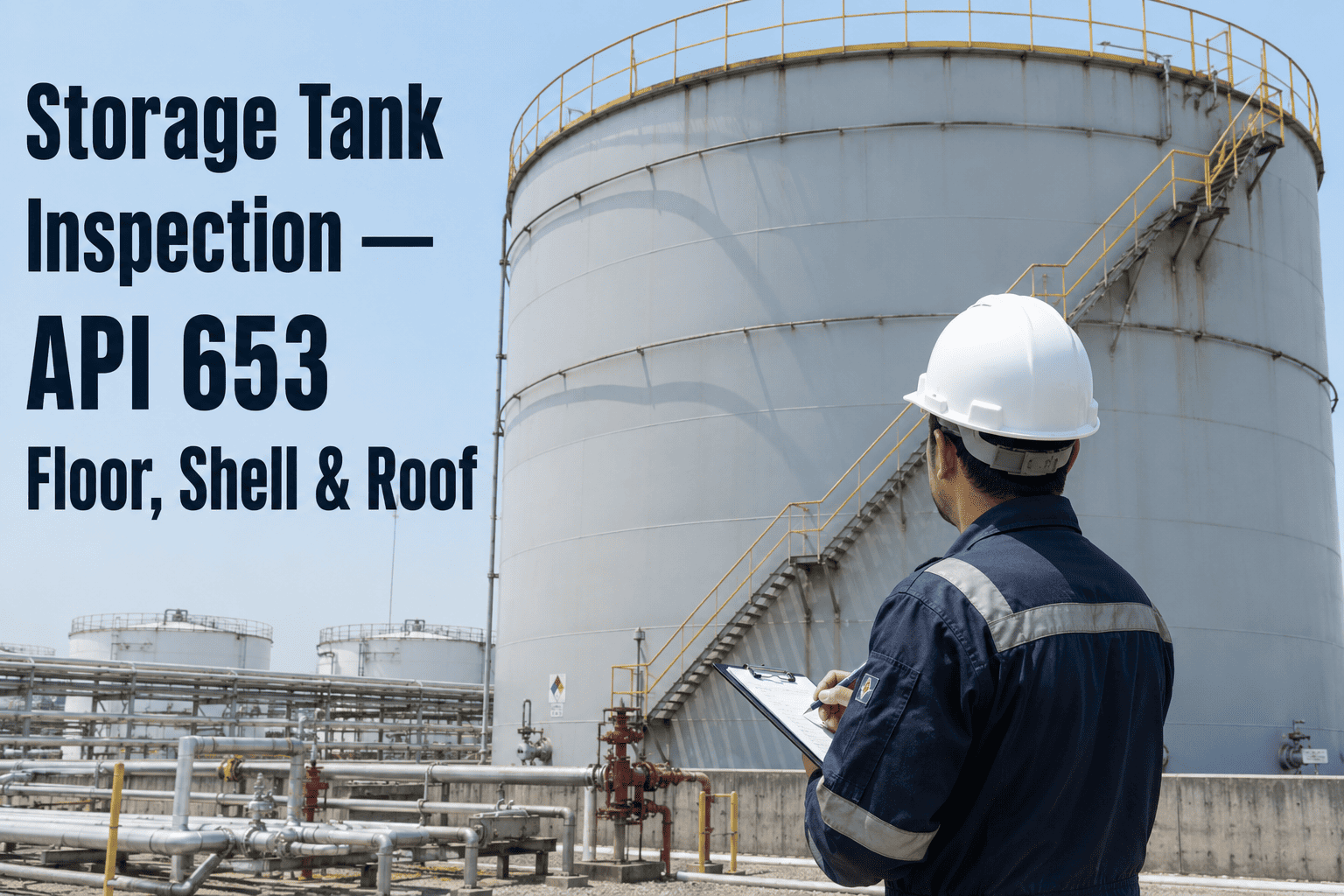
Most aboveground storage tank failures don't start with a dramatic event — they start with a corrosion pit on the underside of a floor plate that nobody could see, growing quietly for years under a layer of sediment and product. By the time a tank shows a visible leak or a shell bulge, the underlying deterioration has usually been progressing since well before the last scheduled inspection. API 653 exists precisely because tank floors, shells, and roofs each fail in different ways and on different timelines, and a single visual walk-around catches almost none of it. For terminal operators, tank farm managers, and API 653 inspectors, the real work is connecting three separate data sources — floor scanning, shell thickness, and settlement survey data — into one picture of tank condition that actually predicts where the next problem will show up. Our support team can walk through how that connected picture applies to your own tank farm.
Three Zones, Three Failure Modes: Floor, Shell, and Roof
A storage tank is really three separate structures bolted together, and each one deteriorates through a different mechanism that requires its own inspection method to catch early.
Treating these three zones as one integrity picture rather than three separate reports matters because failure modes in one zone often show up as early signals in another. A floor settling unevenly at the edge places extra stress on the lowest shell course right above it — the same course a shell UT survey is already measuring. A roof rafter showing early corrosion can point to a ventilation or coating problem that is also accelerating shell-side atmospheric corrosion just below the roof line. Inspectors who review floor, shell, and roof data together, rather than in isolation, are far more likely to catch these compounding patterns before they reach a threshold that forces an unplanned repair.
The Three Inspection Types API 653 Actually Requires
Confusion about which inspection applies when is one of the most common gaps in tank integrity programs — each of the three inspection types under API 653 has its own scope, method, and maximum interval, and mixing them up in a compliance calendar is one of the easiest ways to miss a required inspection window without realizing it until an auditor or regulator points it out.
| Inspection Type | Maximum Interval | Scope | Primary Methods |
|---|---|---|---|
| Routine In-Service | Monthly to annually | Visual walk-around while the tank remains in operation | Visual observation, leak checks, coating condition |
| External | Every 5 years, or sooner based on corrosion rate | Shell exterior, roof, nozzles, insulation, foundation, secondary containment | Visual inspection, external UT thickness spot checks |
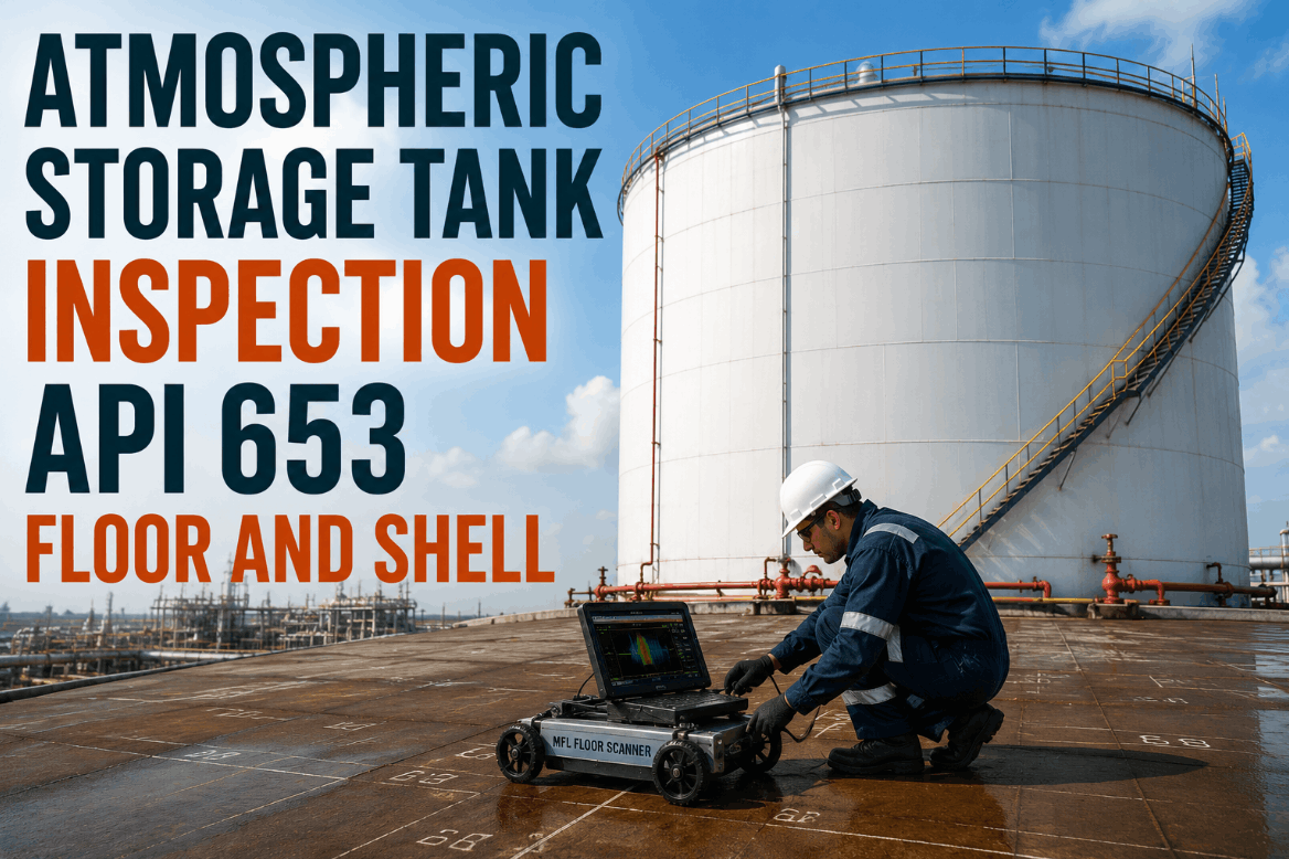
| Internal (Out-of-Service) | Every 10 years, or sooner based on corrosion rate | Tank bottom, shell interior, roof structure, welds, cathodic protection | MFL floor scanning, UT thickness mapping, vacuum box weld testing |
Reading a Settlement Survey Correctly
A tank sitting slightly unevenly on its foundation is normal — but the pattern of that unevenness determines whether it is a maintenance footnote or a structural risk, and API 653 Annex B lays out four recognized patterns.
The entire tank sinks evenly. Generally low risk to the shell itself, but can strain attached piping and nozzle connections over time.
The whole tank tilts uniformly in one direction. Can misalign floating roof seals and place uneven load on nozzles and stairways.
The perimeter settles more than the center, inducing localized shell stress right where the floor-to-shell weld is most vulnerable — this pattern carries a mandatory NDE trigger under Annex B.
The center of the floor sinks relative to the edges, creating a risk of bottom plate buckling and stress concentration near the center of the tank.
A single settlement survey only tells you where a tank sits today. The pattern only becomes actionable once it's compared against at least one prior survey, because a tank showing two inches of edge settlement that has been stable for a decade carries a very different risk profile than a tank showing the same two inches after just two years in service. Digitizing survey elevation data and comparing successive surveys automatically against the Annex B thresholds — rather than re-plotting each new survey by hand — is what turns a settlement inspection from a compliance checkbox into an early warning system for foundation and shell problems.
What Connected Tank Integrity Data Is Worth
Floor scans, shell readings, and settlement surveys are frequently collected by three different contractors, stored in three different formats, and never actually compared against each other in one place — which means corrosion rate calculations often default to conservative assumptions rather than the tank's real measured history. Bringing this data together changes both the inspection interval decision and the capital planning conversation around repair or replacement. Book a demo to see how a connected corrosion-rate model would recalculate re-inspection intervals across your own tank fleet.
| Value Area | Typical Impact | Basis |
|---|---|---|
| Extended internal inspection interval | Up to the full 10-year maximum, versus a conservative default of 5-7 years | Documented, plate-level corrosion rate trend rather than a single historical reading |
| Reduced inspection downtime | Up to 60% less turnaround time per internal inspection | Robotic floor scanning and drone-based roof inspection replacing man-entry and scaffolding |
| Avoided emergency repair costs | Repair scope planned months ahead rather than discovered mid-outage | Corrosion trend flags on high-risk zones ahead of the scheduled inspection date |
| Settlement risk visibility | Early identification of edge or dish-shaped settlement before shell stress becomes critical | Digitized settlement survey data compared against Annex B thresholds automatically |
Turning Raw Readings Into a Corrosion Rate Model
Every UT reading and MFL scan result is, on its own, just a number attached to a location. The value only appears once those numbers are organized into a persistent condition monitoring location network for each tank, so that a reading taken this year can be compared directly against the reading taken at the same physical spot five or ten years ago. That comparison is what produces a defensible corrosion rate — long-term rate calculated across the full measurement history, and short-term rate calculated from the two most recent readings, with API 653 requiring the governing, more conservative of the two to drive the remaining-life calculation. Facilities that have historically used different contractors for each inspection cycle often discover, the first time they consolidate this data, that their monitoring locations don't even line up precisely between surveys, which quietly forces a more conservative corrosion rate assumption than the tank's actual condition would justify. Standardizing the CML network once, and holding every future survey to that same grid, is what lets a decade of data compound into a genuinely tight remaining-life estimate rather than resetting the uncertainty every single inspection cycle.
This same discipline extends to how repair and replacement decisions get made. A monitored location trending toward minimum required thickness ahead of schedule can be flagged years in advance, giving a tank farm operator time to plan a plate replacement into the next scheduled internal inspection rather than discovering the issue during the inspection itself and scrambling to source repair material and schedule welding crews on short notice. The same logic applies to shell courses — a course thinning noticeably faster than the courses above and below it is often an early signal of a localized corrosion mechanism, such as a coating failure or a process-side chemical interaction, that is worth investigating well before it becomes a code-driven repair requirement.
An Inspector's Perspective on What Actually Predicts Tank Failure
I've been an API 653 inspector for over eighteen years, and if there's one thing that consistently surprises tank owners, it's how much of the real risk sits in data they already have but have never looked at together. I've seen tanks where the floor scan showed an isolated pitting cluster right at the shell-to-bottom weld, the settlement survey showed early edge settlement on the same side of the tank, and nobody had connected the two because they came from different reports filed a year apart. Individually, neither finding triggered an immediate action. Together, they described a tank that needed attention well before its next scheduled internal inspection. Once we started reviewing floor, shell, and settlement data as one integrated picture rather than three separate checkboxes, we caught two tanks heading toward exactly that kind of combined failure mode, and both were repaired on a planned schedule instead of an emergency one.
Frequently Asked Questions — API 653 Tank Inspection
The maximum interval is 10 years, but the code requires the actual interval to be based on the shorter of that maximum or a calculation using the measured corrosion rate against the minimum required thickness at each monitored location. In practice, that means a tank with a well-documented, consistent floor scan and shell UT history can often justify running closer to the full 10-year interval, while a tank with sparse or inconsistent historical data defaults to a more conservative interval because the corrosion rate can't be established with confidence. Consolidating scan history from multiple prior inspections into one continuous record is usually the single biggest factor in whether a tank can safely extend toward that maximum. Contact support to see how this calculation would apply to a specific tank in your fleet.
Magnetic flux leakage scanning magnetizes the floor plate and detects changes in the magnetic field caused by pitting, thinning, or flaws, making it especially effective at covering large areas of a tank bottom quickly and locating bottom-side corrosion that isn't visible from above. Ultrasonic thickness testing, by contrast, measures the actual remaining wall thickness at specific grid points using a handheld or automated probe, and is typically used to confirm and quantify anomalies that MFL scanning has already flagged. The two methods work together — MFL for broad area coverage and defect location, UT for precise thickness confirmation at the locations that matter most for corrosion rate calculations.
Edge settlement is the pattern that carries the most immediate concern under API 653 Annex B, since it induces concentrated stress right at the floor-to-shell weld and can trigger a mandatory nondestructive examination requirement once measured values exceed the applicable threshold. Uniform settlement is generally the lowest-risk pattern structurally, though it can still create problems for attached piping and nozzles over time. Planar tilt and dish-shaped settlement fall in between, with risk depending heavily on magnitude and rate of progression rather than the pattern type alone. Tracking settlement survey data over multiple inspection cycles, rather than treating each survey as an isolated snapshot, is what actually reveals whether a pattern is stable or accelerating.
Robotic crawlers and drone-mounted sensors have significantly reduced how much man-entry work is required, particularly for floor scanning, shell thickness mapping, and roof inspection on tanks that can remain partially in-service during the process. That said, certain elements of a full API 653 internal inspection — including detailed visual assessment of welds, coating condition, and specific NDE follow-up on flagged anomalies — still typically require some level of direct access. The realistic picture for most facilities is a hybrid approach, where robotic and drone methods handle the bulk of the scanning work and dramatically cut the time and risk associated with the inspection, while a certified inspector still reviews and signs off on the findings.
Historical MFL floor scan reports, UT readings, and settlement survey data — whether stored as PDFs, spreadsheets, or CSV exports from field instruments — are imported and mapped to a registered condition monitoring location network per tank, building one continuous measurement record instead of a series of disconnected reports. From there, corrosion rate recalculations, remaining-life projections, and inspection interval determinations feed directly into the CMMS platform your team already uses, generating work orders automatically when a tank approaches its next required inspection or when a monitored location crosses a defined threshold. Book a demo to see this working against your own historical tank records.