A pipeline does not fail at the rectifier — it fails at the holiday in the coating that the rectifier was supposed to keep polarized, weeks or months after the rectifier output drifted and nobody caught it. Cathodic protection is the single largest line of defense against external corrosion on buried steel, and the entire system stands or falls on three things working together: rectifier output staying within design range, anode bed condition holding up, and pipe-to-soil potentials across the whole route actually meeting the criteria in NACE SP0169 (now AMPP SP21169). Most operators have the regulatory cadence — six rectifier checks a year under 49 CFR 192.465, periodic close-interval surveys — but the data from each of those checks usually lives in a different binder, spreadsheet, or contractor report. That gap is where protected pipe quietly becomes unprotected pipe.
Is Your CP Monitoring Data Connected — Or Just Compliant?
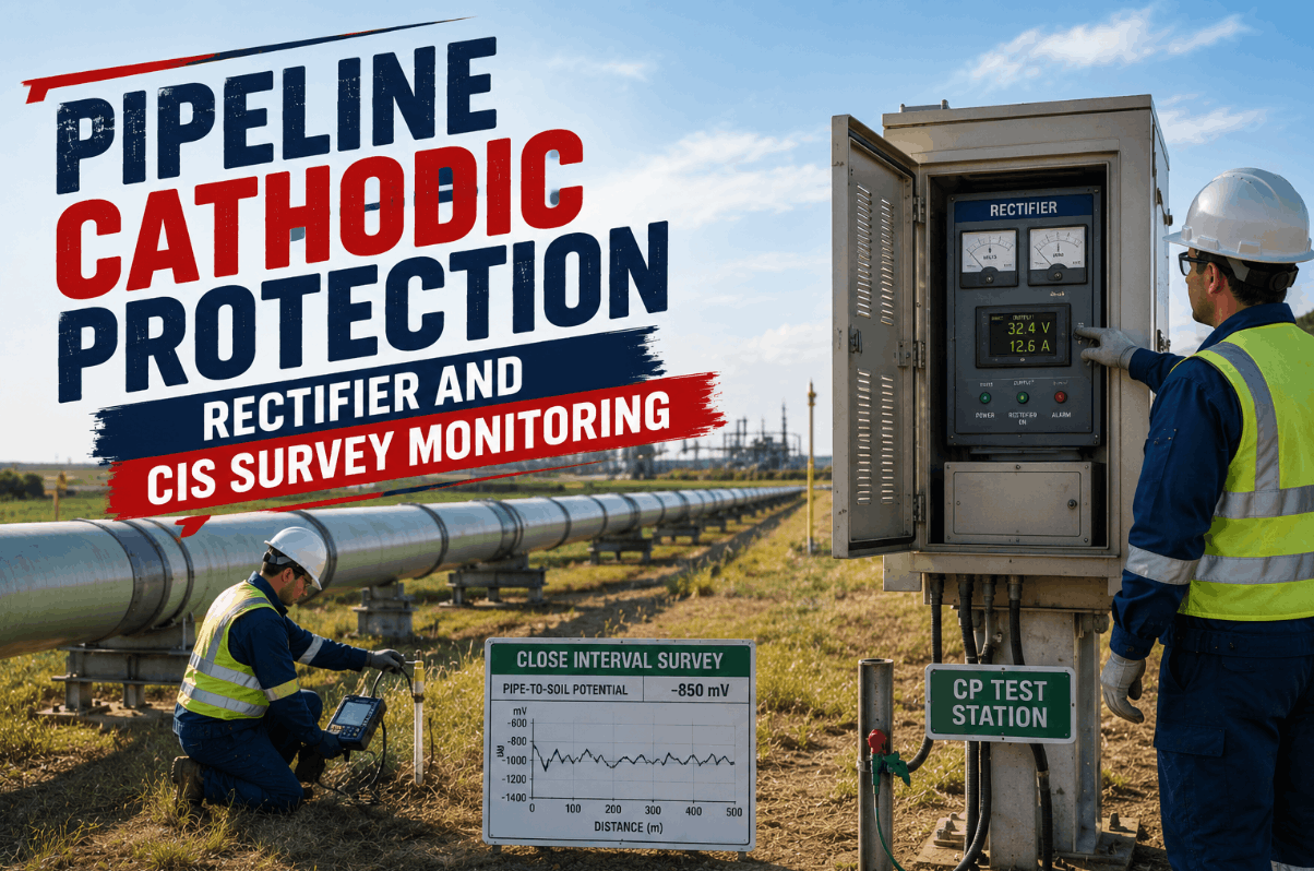
Unify rectifier readings, anode bed condition, test station potentials, and close-interval survey data into one analytics layer built for pipeline corrosion control teams.
Why Rectifier Monitoring Alone Is Not the Same as Proving Cathodic Protection
A rectifier reading within range tells you the power source is working. It does not tell you whether the pipe a half-mile downstream is actually receiving enough current to meet the protection criteria — that depends on anode bed condition, soil resistivity, coating quality, stray current interference, and a dozen other variables that change with the seasons. NACE SP0169 sets the bar at a polarized potential of -850 mV or more negative versus a copper/copper sulfate reference electrode, or a minimum of 100 mV of cathodic polarization — and proving either one requires test station readings and survey data, not just rectifier output. Operators who book a demo with iFactory typically discover their rectifier logs, test station readings, and survey reports have never been cross-referenced against each other in one place — which means deficient segments can sit undetected between the periodic checks that are happening on schedule.
The shift from a compliance-driven CP program to a genuinely protective one starts with connecting these three data streams continuously rather than reviewing them in isolation once or twice a year. iFactory's analytics layer ingests rectifier telemetry, anode bed inspection history, and close-interval survey potentials into a single corrosion control record — so a drifting rectifier, a degrading anode bed, and a marginal potential reading at a specific station number are visible as one connected picture, not three separate filing systems.
Rectifier Output Tracking
Continuously log DC voltage and current against design baselines for every rectifier on the system, flagging drift long before the next 2.5-month manual check would catch it.
Anode Bed Condition Modeling
Track anode consumption rate, ground bed resistance trends, and current distribution to flag anode beds approaching depletion before output capacity is compromised.
Test Station & CIS Integration
Map annual test station potentials and close-interval survey results to station numbers, building a continuous potential profile that highlights where protection is marginal.
Interference & Stray Current Detection
Identify potential shifts consistent with dynamic stray current or telluric interference, distinguishing genuine CP deficiency from a transient external effect.
The CP Adequacy Criteria iFactory Tracks Against NACE SP0169
SP0169 gives operators more than one acceptable way to demonstrate adequate cathodic protection, and the right criterion depends on pipeline conditions, instrumentation access, and whether rectifiers can be safely interrupted for "instant-off" readings. iFactory's analytics platform is built to track all of the commonly applied criteria side by side, so corrosion engineers can document whichever standard fits a given segment without re-engineering their data pipeline. Teams that book a demo generally want to see how their existing test station history maps onto these criteria before committing to a new survey scope.
| Criterion | Measurement Basis | Typical Use Case | Data iFactory Tracks | Survey Demand |
|---|---|---|---|---|
| -850 mV Polarized Potential | Instant-off potential vs. Cu/CuSO4 reference | Most common criterion, rectifiers interruptible | Instant-off readings at every test point | High |
| 100 mV Cathodic Polarization | Shift between native and polarized potential | Where native potential baseline is documented | Native potential history plus depolarization data | Moderate |
| "On" Potential Survey | Potential measured with CP energized | Rectifiers that cannot be safely interrupted | Continuous on-potential profile by station | Standard |
| Close-Interval Survey (CIS) | Pipe-to-soil potential at close-spaced intervals | Targeted assessment between test stations | Full potential profile, anomaly flagging by location | High |
How iFactory Keeps Your Rectifier and CIS Cadence Audit-Ready
49 CFR 192.465 and 195.573 set the regulatory floor for CP monitoring: rectifiers checked six times per year with no gap exceeding 2.5 months, remotely monitored rectifiers physically verified at least once every 15 months, and close-interval surveys triggered when annual test station readings show localized deficiency rather than a systemic issue. Meeting that cadence on paper and proving it with defensible data are two different exercises — the second is where most corrosion control teams lose time during an audit.
Rectifier Inventory and Telemetry Connection
Register every rectifier with design output range, anode bed configuration, and interruption capability. Connect remote monitoring units or scheduled field readings into a single timestamped record.
Test Station and Survey Data Ingestion
Import annual test station potentials and historical CIS results, mapped to station numbers and route mileage, so every reading has a defined location and a comparison baseline.
Criteria-Based Adequacy Scoring
Score each segment against the applicable SP0169 criterion — -850 mV instant-off, 100 mV polarization, or on-potential — and flag readings that fall short or trend toward marginal.
Deficiency-Triggered CIS Recommendation
When a test station reading indicates localized rather than systemic deficiency, the platform flags the segment as a CIS candidate per the close-interval survey trigger criteria.
Inspection Cadence and Remediation Tracking
Track every rectifier check against the 2.5-month interval and every remote-monitored unit against the 15-month physical inspection requirement, with remediation timelines logged for any deficient finding.
In nearly two decades of corrosion control work, the deficiency I see most often is not a missing rectifier check — it's a rectifier check that passed in isolation while the test station data three miles away was already trending toward -800 mV. SP0169 gives you the criteria, but it does not connect your data for you. The operators with the strongest CP programs are the ones who treat rectifier output, anode bed condition, and survey potentials as one dataset instead of three separate logs that only get compared once a year during the integrity review.
Where Cathodic Protection Programs Most Often Fall Short
Most operators pursuing improvements to their cathodic protection program encounter a predictable set of data and documentation gaps. Recognizing these patterns before an audit or, worse, a corrosion-related leak, helps corrosion control engineers prioritize where to focus limited survey and remediation budget.
Rectifier readings are checked against design range but never cross-referenced with downstream test station data, so localized deficiency goes unnoticed between surveys.
Without trending ground bed resistance over time, anode consumption approaching end-of-life is discovered only when output capacity has already dropped.
Survey results delivered as a contractor PDF rather than structured, location-tagged data make year-over-year comparison at a specific station number a manual exercise.
A potential shift caused by stray current or telluric activity is mistaken for genuine CP deficiency, triggering unnecessary remediation while the real cause goes unaddressed.
Different segments are evaluated against different SP0169 criteria without documentation of which criterion applies where, creating ambiguity during an audit.
Deficient findings are logged but remediation completion dates are not tracked against the timelines expected by regulators, leaving open findings to age past acceptable limits.
Closing these gaps requires connecting rectifier telemetry, anode bed history, and survey data into one structured record rather than adding another standalone tracking spreadsheet. Corrosion control teams regularly book a demo to see how their current CP data maps onto this kind of unified record.
Connect Your Rectifier, Anode Bed, and CIS Data Into One Record
iFactory's corrosion control analytics platform brings rectifier telemetry, anode bed condition, and close-interval survey potentials together so your CP program is documented as one connected system, not three separate logs.
Pipeline Cathodic Protection Monitoring — Common Questions Answered
How often must rectifiers be inspected under federal regulation?
Six times per year with no gap exceeding 2.5 months under 49 CFR 192.465; remotely monitored rectifiers also need a physical inspection at least once every 15 months.
What potential criteria does NACE SP0169 accept as proof of adequate CP?
A polarized potential of -850 mV or more negative versus a Cu/CuSO4 reference electrode, or a minimum of 100 mV of cathodic polarization, are the two most commonly applied criteria.
When is a close-interval survey required versus an annual test station reading?
A CIS is typically triggered when annual test station data shows localized rather than systemic deficiency, providing a continuous potential profile to isolate the affected segment.
How does iFactory distinguish a real CP deficiency from stray current interference?
By trending potential shifts against rectifier output and known interference sources over time, the platform flags transient interference patterns separately from sustained deficiency.
Can iFactory work alongside our existing CIS survey contractor?
Yes — iFactory ingests survey results from any contractor's data format and maps them to station numbers alongside rectifier and test station history for continuous comparison.