Subsea pipelines spend their entire service life in an environment nobody can walk up to and inspect by eye, which is exactly why free spans, coating breakdown, and cathodic protection depletion can progress for years before a routine survey finally catches them. A pipeline sitting on an unstable seabed can develop a free span from current-driven scour long before any topside pressure or flow anomaly gives a hint that something has changed below the waterline. ROV-based visual inspection paired with cathodic protection anode surveys remains the most reliable way to catch these issues while they are still manageable repairs rather than integrity emergencies, and getting inspection scope, interval, and reporting right across a pipeline network is where most integrity teams need the strongest support, something iFactory's support documentation covers in more detail.
01 / What A Submarine Pipeline Survey Actually Covers
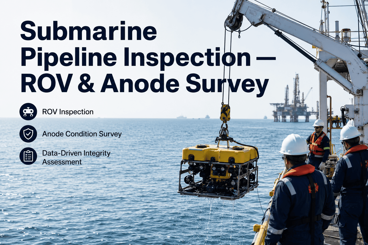
A complete submarine pipeline integrity survey combines several distinct inspection disciplines run from the same ROV spread, each targeting a different failure mode that a subsea pipeline can develop over its service life.
02 / Free Span Management — Reading The Numbers Right
Not every free span requires immediate remediation, and treating every span the same way either wastes intervention budget on stable spans or leaves a genuinely risky one unaddressed until the next survey cycle.
03 / Cathodic Protection — Reading An Anode Survey Correctly
Sacrificial anode systems protect subsea pipeline steel for decades, but anode consumption is rarely uniform along a route, and a survey that only reports an average pipeline potential can mask a localized section running dangerously close to unprotected.
| Survey Finding | What It Indicates | Typical Response |
|---|---|---|
| Potential Within Protective Range | Cathodic protection is functioning as designed along that section | No action beyond routine resurvey interval |
| Potential Trending Toward Threshold | Anode capacity depleting faster than design life assumed | Shorten resurvey interval and plan retrofit anode sled |
| Potential Outside Protective Range | Section is at active corrosion risk without adequate CP coverage | Prioritize retrofit anode installation ahead of next cycle |
| Localized Anomalous Reading | Possible coating damage or holiday exposing bare steel | Targeted follow-up visual inspection at that location |
04 / Seabed Stability And Burial Verification
Trenched and buried pipeline sections are designed assuming a stable cover depth, but storm events, current shifts, and seabed mobility can expose or partially uncover sections that were buried at installation.
05 / Planning A Survey Campaign Around Actual Risk
An efficient ROV survey campaign does not treat every kilometer of pipeline the same way. Route sections near platforms, crossings, and known scour-prone seabed typically warrant closer visual attention and more frequent multibeam passes than long, stable, buried stretches with a clean inspection history. Building the survey scope around a risk-ranked route map, rather than a uniform sweep, lets the ROV spread spend more time where findings are actually likely and less time re-confirming sections that have shown no change across several prior campaigns. This approach also tends to reduce total vessel days for a given level of assurance, since survey time is allocated to risk rather than distance alone.
06 / Common Survey Findings And What They Usually Mean
Most subsea pipeline surveys turn up a familiar set of findings repeatedly, and knowing what each typically indicates helps an integrity team triage results quickly rather than treating every anomaly as equally urgent. Localized coating disbondment without exposed steel is common and usually scheduled for monitoring rather than immediate repair, while exposed steel with an active CP reading outside protective range moves to a higher priority. A newly detected free span with no prior history at that location often reflects a recent seabed event and typically warrants a shorter resurvey interval even if the span itself is still within allowable length, simply to confirm whether it is stabilizing or continuing to grow before deciding on remediation.
07 / Building A Defensible Subsea Integrity Record
Regulators and joint venture partners increasingly expect subsea pipeline operators to demonstrate a consistent, trackable integrity history rather than a folder of disconnected survey reports from different contractors and years. When ROV visual findings, CP survey results, and free span measurements are tracked together over successive campaigns, integrity teams can show a defensible trend rather than a single point-in-time snapshot, which matters considerably during regulatory audits and asset transfer due diligence. Facilities that consolidate this history in one place also find repeat findings — a slowly growing span, a section trending toward CP threshold — get caught early because the comparison across survey years is immediate rather than requiring someone to pull and compare old PDF reports manually.
08 / Conclusion — Consistency Across Survey Cycles Is The Real Value
A single ROV survey is a snapshot, but a subsea pipeline's real integrity story only becomes visible when successive surveys are compared against each other consistently over years of service life. Book a demo to see how your existing survey history could be organized into a continuous integrity record.
Frequently Asked Questions — Submarine Pipeline Inspection
Survey intervals are typically set through a risk-based inspection process that accounts for pipeline age, product carried, water depth, seabed conditions, and any findings from prior surveys rather than a single fixed interval applied uniformly across a network. Newer pipelines in stable seabed conditions with clean prior survey history often move to longer intervals, while sections with a known free span trend, CP readings approaching threshold, or history of third-party interference typically warrant more frequent monitoring. Regulatory requirements in the operating jurisdiction also factor into minimum interval requirements regardless of what a purely risk-based assessment alone would suggest. iFactory's support documentation covers common interval frameworks used across different regulatory regimes.
The decision typically weighs span length against the allowable span length calculated from fatigue and vortex-induced vibration analysis for that specific pipe size, wall thickness, and current environment, alongside the span's growth trend across successive surveys. A span within allowable limits and showing no significant growth between surveys is usually left under continued monitoring, while a span approaching or exceeding its calculated allowable length, or one growing rapidly between survey cycles, typically moves to remediation planning such as rock dumping, grout bags, or a support saddle installation. Growth rate carries particular weight in this decision because a stable span at a given length carries meaningfully less risk than a span still actively lengthening toward that same value.
Comparing survey data across contractors and years is one of the more common practical challenges in subsea pipeline integrity management, since reporting formats, camera positioning, and even chainage referencing conventions can vary between contractors performing successive surveys on the same pipeline. Establishing a consistent internal reference system — typically anchored to fixed pipeline features or a standardized chainage convention — before commissioning each new survey campaign is the most reliable way to keep comparisons meaningful over time. Organizing findings into a structured, contractor-independent record rather than relying on each contractor's individual report format is what ultimately makes multi-year trend comparison practical.
When an anode survey shows potential readings trending toward or past the protective threshold along a section of pipeline, the typical response is installation of retrofit anode sleds or bracelet anodes at that location to restore adequate protection before active corrosion can begin on the exposed steel. The specific retrofit approach depends on pipeline diameter, water depth, and access constraints at that section, and is usually planned well ahead of the point where potential readings actually cross the unprotected threshold rather than after the fact. Tracking anode depletion trend across survey cycles, rather than relying on a single reading, is what gives integrity teams the lead time to plan and budget for retrofit work on a normal schedule.
ROV visual inspection covers surface condition, coating damage, and visible free spans effectively, but it is typically paired with multibeam bathymetric survey for accurate span geometry measurement and with cathodic protection potential surveys for corrosion protection assessment, since none of these methods alone gives a complete integrity picture. Digital or intelligent pigging, where the pipeline configuration allows it, adds internal wall thickness data that external ROV survey cannot provide. Most comprehensive subsea integrity programs combine several of these methods on a staggered schedule rather than running every method on every survey cycle, balancing coverage against the cost of each survey type. Book a demo to discuss a survey method mix suited to your pipeline network.


.png)