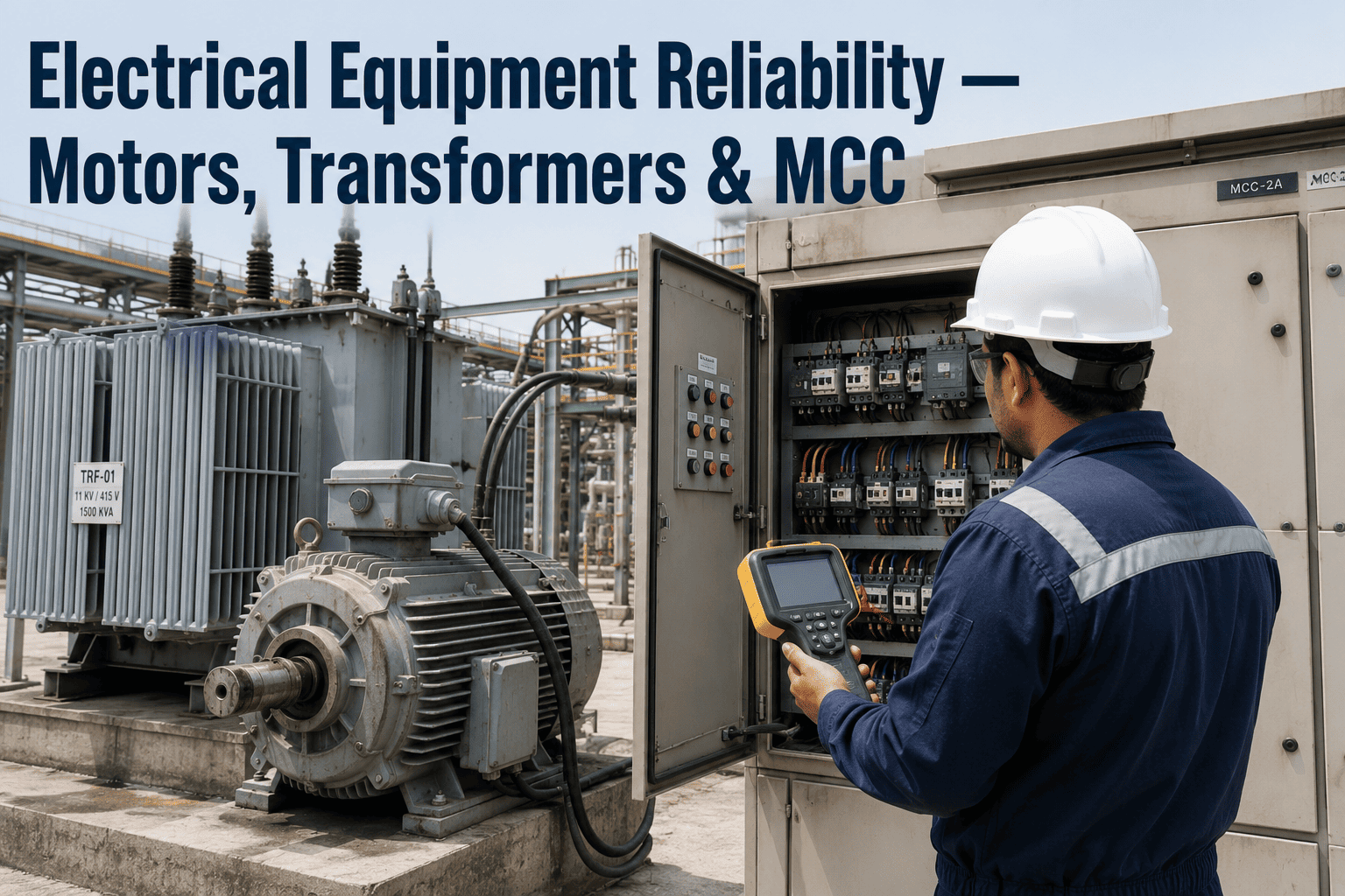
Electrical failures rarely happen without warning — a transformer that fails catastrophically has usually been generating detectable fault gases in its oil for three to twelve months beforehand, and a motor that trips offline unexpectedly has typically shown electrical signature changes 60 to 120 days before the fault became mechanically obvious. The problem in most oil and gas facilities is not that the warning signs don't exist, it is that nobody is systematically watching for them across the full scope of electrical equipment that keeps a plant running — motors, transformers, switchgear, and motor control centers each have their own failure modes and their own early indicators, and a reliability program that only covers one or two of these domains leaves the others to fail reactively. This page walks through what a genuinely comprehensive electrical equipment reliability program looks like across all four domains, and how to see the same monitoring approach applied to your own plant's electrical assets.
Why Electrical Failures Cost More Than Almost Any Other Asset Class
Electrical equipment failures in an oil and gas plant carry a cost structure unlike most mechanical asset classes — the direct repair or replacement cost is often the smallest part of the bill. A single unplanned motor failure typically runs $15,000 to $50,000 once lost production, emergency repair labor, and downstream process impact are counted, and that number climbs sharply for larger drive motors on critical process lines. A high-voltage circuit breaker failure at a large generation or process unit during peak operation can represent a far larger single-event revenue loss, and transformer replacement on a reactive, unplanned basis typically costs a significant multiple of what planned end-of-life management would have cost with proper condition history in hand. The pattern across all four equipment domains is the same: the equipment usually tells you it is failing well in advance, and the cost difference between catching that signal early and missing it is not incremental — it is categorical.
Motors, Transformers, Switchgear, and MCC Each Fail Differently
A reliability program built around a single test method inevitably has blind spots, because motors, transformers, switchgear, and motor control centers fail through genuinely different physical mechanisms and require different diagnostic approaches to catch early. Understanding what each domain actually needs is the starting point for building a program that covers the full electrical system rather than just the equipment that happens to be easiest to test. A plant that has excellent transformer DGA data but no coordinated motor testing program has simply moved its blind spot from one equipment class to another, and the unplanned failure still shows up on the schedule eventually — just in a different domain than the one being watched.
Motors
Broken rotor bars, bearing degradation, air-gap eccentricity, and winding faults show up in the motor's electrical current signature well before they become mechanically detectable, making current-based testing the earliest available warning system for rotating equipment.
Transformers
Thermal faults, partial discharge, and cellulose insulation aging generate specific combustible gases that dissolve into the insulating oil, giving dissolved gas analysis a multi-month lead time on developing internal faults.
Switchgear
Contact resistance degradation, circuit breaker timing drift, and insulation aging accumulate slowly on equipment that may operate infrequently, which is exactly why scheduled testing rather than run-to-failure monitoring matters most here.
Motor Control Centers
Loose connections and degrading components in MCC buckets reveal themselves through rising temperature at the connection point, long before the fault progresses to arc flash risk or a tripped breaker.
Motor Current Signature Analysis and Motor Circuit Analysis
Motors consume the largest share of electricity in an industrial facility and drive nearly every critical rotating asset on-site, which is exactly why motor testing delivers some of the fastest measurable return of any electrical reliability program. Motor Current Signature Analysis (MCSA) monitors the electrical current a motor draws while it continues running, detecting developing faults without ever taking the equipment offline. Motor Circuit Analysis (MCA) complements this with offline testing of the full motor circuit — cables, connections, and windings — identifying whether a developing problem originates in the motor itself or upstream in the supply circuit.
Baseline Signature Capture
Initial current and circuit measurements establish a healthy baseline for each motor, giving every future test a reference point for detecting genuine deviation.
Ongoing MCSA Monitoring
Electrical signature is tracked continuously or on a defined interval, surfacing rotor bar, bearing, and eccentricity faults 60 to 120 days ahead of mechanical symptoms.
MCA Circuit Verification
Periodic offline testing evaluates the full circuit from MCC bucket to motor winding, isolating whether a flagged issue sits in the motor or the supply path.
Combined Health Scoring
MCSA and vibration data combined detect a documented 94% of developing faults, compared to roughly 55 to 65% from vibration monitoring used alone.
Dissolved Gas Analysis and Oil Quality Monitoring
Dissolved Gas Analysis remains the industry standard for assessing the internal condition of an oil-filled transformer, because the insulating oil itself carries direct chemical evidence of what is happening inside the tank. As internal faults develop — overheating from poor cooling or high current loads, partial discharge, arcing, or cellulose insulation breakdown — the oil absorbs specific combustible gases in patterns that trained analysis can trace back to a fault type and severity. A transformer showing rising hydrogen levels month over month, for instance, is telling you something specific about a developing internal condition well before that condition becomes an unplanned outage.
Fault Gas Identification
Hydrogen, methane, ethylene, acetylene, and carbon oxide concentrations are interpreted against established industry ratio methods to classify overheating, partial discharge, or arcing conditions.
Trend-Based Alerting
Individual gas readings matter less than the rate of change over time — a rapid rise in a key fault gas over consecutive samples is a stronger signal than any single elevated reading.
Cellulose Insulation Aging
Furan compound analysis assesses the condition of the paper insulation directly, since cellulose degradation is what ultimately governs a transformer's useful remaining life.
Oil Quality Parameters
Breakdown voltage, moisture content, and acidity are tracked alongside dissolved gas data to build a complete picture of the oil's continued ability to insulate and cool the unit.
Switchgear Condition Testing and MCC Thermal Monitoring
Switchgear presents a distinct reliability challenge because it is frequently designed to operate infrequently — a circuit breaker that only interrupts fault current a handful of times across its service life can still develop contact resistance issues or timing drift that only a scheduled test will catch, since there is no continuous operating signal to monitor passively. Motor control centers face the opposite challenge: they operate constantly, and the connection points inside MCC buckets are where loose terminations and degrading contactors reveal themselves first, through a rise in temperature that continuous thermal monitoring can catch without ever opening an energized panel.
| Test / Monitoring Method | Applies To | What It Detects |
|---|---|---|
| Contact resistance testing | Switchgear, circuit breakers | Degrading connections before they generate excess heat under load |
| Circuit breaker timing tests | MV/HV switchgear | Mechanism wear affecting trip and close response times |
| Continuous thermal monitoring | MCC buckets, busbars | Intermittent and gradual heat buildup at connection points |
| Insulation resistance testing | Switchgear, MCC, cables | Insulation aging and moisture ingress before dielectric failure |
| Protection relay testing | Switchgear protection systems | Correct trip settings and relay response under fault conditions |
What Changes When Electrical Maintenance Becomes a Program Instead of a Response
Most oil and gas facilities already run some electrical testing, but it is frequently scattered across different vendors, different schedules, and different documentation systems with no single view connecting the data back to maintenance decisions. A DGA sample gets pulled annually by one contractor, MCSA readings get logged by a different vendor on a different cycle, and switchgear testing happens whenever an outage window allows — each producing a report that sits in its own folder, rarely cross-referenced against the others even though a single unit's motor, its supply breaker, and its feed transformer are all part of the same failure chain. Building a unified reliability program changes what happens between the test and the repair.
- Motor, transformer, and switchgear testing run on separate schedules with separate vendors
- Test results live in disconnected reports rarely reviewed against each other
- Trend analysis is difficult without a consistent historical record
- Corrective work orders created manually after report review, often days later
- Most failures still discovered reactively despite the testing being performed
- All four equipment domains tracked on a coordinated testing and monitoring schedule
- Test results connected to a single asset health record per piece of equipment
- Trend rates calculated automatically against historical baselines
- Threshold crossings generate corrective work orders without manual review lag
- Developing faults caught months ahead of failure, consistently across the fleet
How iFactory Builds a Coordinated Electrical Reliability Program
A turnkey deployment means your reliability team is not left stitching together separate test vendors, spreadsheets, and paper reports into something usable after the fact. iFactory's platform is built to bring motor, transformer, switchgear, and MCC condition data into one system connected directly to maintenance work orders, so a threshold crossing on any piece of equipment turns into an action item automatically rather than a report someone has to notice.
Asset Inventory & Baseline
Every motor, transformer, switchgear assembly, and MCC on-site is cataloged, with baseline condition data captured for future trend comparison.
Test Schedule Coordination
MCSA, MCA, DGA sampling, switchgear testing, and MCC thermal monitoring are scheduled and tracked from a single system rather than four disconnected calendars.
Automated Threshold Alerting
Industry-standard thresholds for each test type generate corrective work orders automatically the moment a reading crosses into concerning territory.
Fleet-Wide Trend Visibility
Reliability teams get a single dashboard view across every electrical asset class, replacing the scattered reports that previously made fleet-wide risk difficult to see.
Frequently Asked Questions
Bring All Four Electrical Domains Into One Reliability Program
iFactory connects motor current signature analysis, transformer dissolved gas analysis, switchgear condition testing, and MCC thermal monitoring into a single system — turning test results into maintenance action automatically, months before a failure would otherwise occur.