A standard industrial camera housing will not survive certification testing in a Zone 1 refinery unit, and the reason has nothing to do with build quality — it has to do with what the housing is actually designed to contain. An Ex d enclosure is not rated by how well it keeps dust and moisture out. It is rated by how reliably it contains an internal explosion long enough to cool the escaping gases below their ignition temperature before they reach the surrounding atmosphere. That is a fundamentally different engineering problem than weatherproofing, and it changes every decision about wall thickness, flame path tolerance, and cable gland selection for the camera, LiDAR, or gas sensor sitting inside. If your robotics or fixed-monitoring program is scoping hazardous-area sensor housings for the first time, talk through the design requirements with the iFactory team.
Design Reference · Hazardous Area Sensor Enclosures
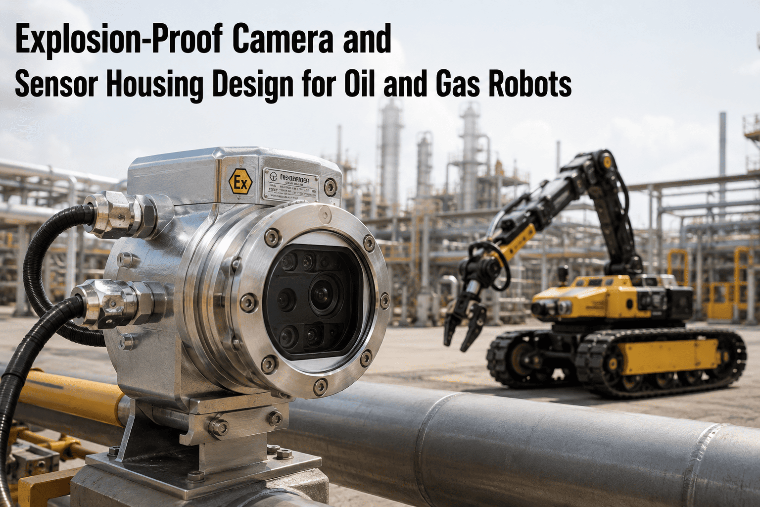
Explosion-Proof Camera and Sensor Housing Design for Oil and Gas Robots
A design engineer's reference for choosing between Ex d flameproof and Ex p pressurized enclosure strategies when the payload is a camera, LiDAR unit, or gas sensor operating in a Zone 1 or Zone 2 environment.
IEC 60079
The core standards series governing every Ex protection method covered here
<0.15 mm
Typical maximum flame path gap tolerance required for an Ex d certified joint
5–10x
Enclosure volumes of protective gas purged before power-up on an Ex p system
Zone 0–2
The classification range a sensor housing decision has to account for before design starts
Classification Layer
Zone and Gas Group Come Before Any Enclosure Decision
Enclosure selection is not a preference — it is derived directly from the hazard classification of the space the sensor will occupy. Getting this step wrong invalidates every design decision that follows it, regardless of how well the resulting enclosure is built.
| Zone |
Hazard Presence |
Typical Refinery Location |
Common Protection Methods |
| Zone 0 |
Continuous or long-period presence |
Interior of process vessels, storage tank vapor space |
Intrinsic safety (Ex ia) almost exclusively |
| Zone 1 |
Likely to occur during normal operation |
Pump pads, compressor houses, near flanges and seals |
Ex d, Ex p, Ex ia/ib, Ex e (limited) |
| Zone 2 |
Not likely, and only for short periods if it occurs |
Perimeter walkways, control rooms adjacent to process units |
Ex n, Ex e, Ex ic, most standard-duty Ex-rated equipment |
Gas group — IIA, IIB, or IIC — further narrows the design requirement, since IIC gases such as hydrogen require tighter flame path tolerances than IIA gases such as propane. A housing certified for IIA cannot be assumed safe for a IIC atmosphere without re-qualification.
Protection Method Layer
Ex d and Ex p Are the Two Methods That Actually Fit a Camera or LiDAR Payload
Several protection concepts exist across the IEC 60079 series, but most of them are built for simpler payloads — terminal boxes, motors, junction boxes. A camera, LiDAR unit, or gas sensor has optical windows, active electronics, and often a need for a clear field of view, which narrows the realistic options to two primary strategies.
Ex d — Flameproof
Containment strategy
The enclosure is built strong enough to contain an internal explosion and cool the escaping gases below ignition temperature through precisely machined flame path joints before they reach the outside atmosphere. Construction is typically thick-walled aluminum, cast iron, or steel.
Best fit: fixed cameras and sensors where a compact, self-contained enclosure with no external gas supply is preferred.
Ex p — Pressurized
Exclusion strategy
The enclosure interior is purged with a protective gas and maintained at positive pressure relative to the surrounding atmosphere, physically excluding the hazardous gas from ever reaching the electronics inside. Requires a monitored gas supply and a loss-of-pressure interlock.
Best fit: larger enclosures with multiple sensors, processing electronics, or equipment that would be impractically heavy in a flameproof housing.
Ex e — Increased Safety
Prevention strategy
Prevents ignition sources from forming in the first place through design measures rather than containing them — no arcing or sparking components permitted inside. Lighter construction than Ex d, but generally unsuitable for active camera or LiDAR electronics.
Best fit: passive components such as terminal blocks and cable connections, not sensor payloads.
Ex ia / ib — Intrinsic Safety
Energy-limiting strategy
Limits the electrical energy available in the circuit to a level too low to ignite the atmosphere under fault conditions. Highly effective for low-power sensors, but a full camera or LiDAR payload typically exceeds the energy budget this method allows.
Best fit: low-power field instruments and simple sensors, sometimes paired with Ex d or Ex p for the higher-power components.
Not Sure Which Protection Method Fits Your Deployment
Enclosure Selection Errors Are Expensive to Discover After Fabrication
iFactory works alongside your robotics and instrumentation team to map sensor payloads to the correct Ex protection method before design work begins — avoiding a certification failure after the enclosure has already been built and machined.
Design Considerations Layer
What Changes When the Payload Is a Sensor, Not a Switch
Most Ex d and Ex p reference designs were developed for motors, junction boxes, and control equipment. Cameras, LiDAR units, and gas sensors introduce design constraints that a generic hazardous-area enclosure specification does not fully anticipate.
01
Optical window integrity
A camera or LiDAR needs a clear optical path, which means the enclosure includes a viewport — and that viewport becomes part of the flame path boundary on an Ex d design. Window material, thickness, and the seal around its perimeter all carry their own certification requirements, and a scratched or improperly seated window can invalidate the entire enclosure's rating.
02
Internal heat dissipation
Active electronics generate heat that a sealed Ex d enclosure cannot vent through convection the way an open-air housing would. Internal component layout, heat sink sizing, and in some designs internal fans rated for the enclosure's protection method all need to keep surface temperatures below the ignition point of the surrounding gas group.
03
Cable gland and connector certification
Every cable entry point is a potential flame path breach if the wrong gland is used. Ex d rated glands are mandatory for Ex d enclosures specifically — a standard or Ex e gland on an Ex d housing voids the certification even if the enclosure body itself is fully compliant.
04
Mounting and vibration on a mobile platform
A fixed installation and a robot-mounted sensor experience very different mechanical loads. A housing certified under static test conditions needs additional vibration and shock qualification before it can be trusted on a quadruped or crawler platform moving across uneven refinery terrain.
Sensor-Specific Layer
Gas Sensors Add a Design Constraint Cameras and LiDAR Do Not Have
A camera or LiDAR unit can sit fully sealed behind an optical window with no compromise to its function. A gas sensor cannot — it needs the target gas to physically reach its sensing element, which puts it in direct tension with the containment or exclusion strategy the rest of the enclosure is built around.
Flame arrestor sintered elements
Gas sensors housed in Ex d enclosures typically access the atmosphere through a sintered metal flame arrestor that allows gas molecules through while still quenching any flame that might originate inside the housing — a specialized component with its own certification and periodic inspection requirement.
Response time versus containment tradeoff
A sintered flame arrestor slows gas diffusion to the sensing element compared to an open sensor, which means response time specifications need to be validated with the arrestor installed, not against the bare sensor's datasheet figures.
Calibration access without breaking certification
Field calibration of a gas sensor inside a certified enclosure needs a defined procedure that does not require opening the flame path boundary in a live hazardous area — typically a certified calibration port or a removal-to-safe-area procedure.
Cross-sensitivity in mixed-hazard zones
A gas sensor calibrated for a single target gas can produce misleading readings in a zone where multiple hydrocarbon vapors are present simultaneously, which matters for how alarm thresholds are set on a robot patrolling across several process areas with different gas profiles.
Common Failure Points
Where Sensor Housing Designs Fail Certification or Fail in the Field
Field modification after certification
Drilling an additional cable entry or swapping a component after the enclosure has been certified voids the rating, even when the modification looks minor. Any change requires re-certification by an approved facility, not a field judgment call.
Mismatched gas group rating
Specifying an enclosure rated for IIA or IIB gases and deploying it in a IIC atmosphere — common near hydrogen processing units — is a certification mismatch that is easy to make during procurement and expensive to discover after installation.
Loss-of-pressure interlock gaps on Ex p systems
A pressurized enclosure depends entirely on maintaining positive pressure — a monitoring gap or a delayed alarm on pressure loss defeats the entire protection strategy without any visible sign that something has changed.
Underspecifying vibration tolerance for mobile platforms
An enclosure that passes static certification testing can still develop flame path gap deviations over months of vibration on a mobile robot, particularly at gland entries and seam joints that were torqued correctly at commissioning but loosen under sustained mechanical stress.
Specification Roadmap
From Zone Classification to Certified, Deployed Enclosure
Step 1
Confirm Zone and Gas Group
Document the exact zone classification and gas group for every location the sensor will operate in, including any planned expansion areas — this single input drives every downstream design decision.
Step 2
Select Protection Method
Match the sensor payload's power draw, size, and heat output against Ex d, Ex p, or a hybrid approach — larger multi-sensor payloads often favor Ex p, while single compact cameras often favor Ex d.
Step 3
Design and Prototype
Engineer the flame path joints, viewport seal, cable glands, and thermal management around the selected protection method, then build a prototype for internal validation before submitting for third-party certification testing.
Step 4
Certify and Deploy
Complete IECEx or ATEX certification testing through an approved body, document the certificate conditions precisely, and lock the design against field modification once deployed to preserve the rating.
Standards Reference
Which Standard Governs Which Protection Method
IEC 60079-1
Governs Ex d flameproof enclosure construction, flame path design, and testing requirements — the primary reference for any camera or sensor housing pursuing flameproof certification.
IEC 60079-2
Governs Ex p pressurized enclosure design, including purge cycle requirements, minimum overpressure thresholds, and loss-of-pressure protection interlocks.
IEC 60079-7
Governs Ex e increased-safety equipment, relevant primarily to the terminal and connector components inside a larger sensor enclosure assembly.
IECEx and ATEX Schemes
The certification frameworks that verify compliance with the underlying IEC 60079 standards — IECEx for international recognition, ATEX for the European market, with NEC/CEC equivalents governing North American installations.
Practitioner Perspective
The question I get most often from teams designing their first hazardous-area sensor payload is whether they should default to Ex d because it feels more self-contained. Sometimes that is the right call. But a lot of camera and LiDAR payloads are genuinely better served by Ex p, especially once you start stacking multiple sensors and processing electronics into one enclosure — the weight and thickness penalty of building all of that as flameproof gets impractical fast, particularly on a mobile robot where every extra kilogram affects battery life and mechanical loading. The teams that get this right start from the zone classification and the payload's actual power and heat budget, not from whichever protection method they happened to use on their last project.
Renata Alves
Hazardous Area Equipment Design Engineer · 14 years certifying instrumentation and robotics enclosures for oil, gas, and chemical processing · IECEx-qualified certification body liaison
Frequently Asked
Explosion-Proof Sensor Housing — Common Questions from Design Engineers
Should we choose Ex d or Ex p for a camera and LiDAR payload on a Zone 1 robot?
The decision generally comes down to payload size and power draw. A single compact camera with modest heat output is often a good fit for Ex d, since the enclosure can stay relatively small and self-contained with no external gas supply to manage. A payload combining a camera, LiDAR unit, and onboard processing electronics — which draws more power and generates more heat — often favors Ex p, because building an enclosure that thick and heavy in flameproof construction becomes impractical on a mobile platform where weight directly affects battery runtime and mechanical stress.
Book a design consultation to map your specific payload against both protection methods before committing to a direction.
Can we drill an extra cable entry into a certified enclosure after it arrives from the manufacturer?
No — any modification to a certified Ex d or Ex p enclosure, including drilling, cutting, or machining, voids the certification unless it is performed by an approved manufacturer under controlled conditions. This applies even to changes that seem minor, such as adding a single additional cable gland, because the certification covers the enclosure as tested, not the enclosure as it might reasonably be modified. Any anticipated future cable entries, sensor additions, or connector changes need to be specified before the enclosure goes to certification testing, not added afterward in the field.
What is the practical difference between a gas group IIA, IIB, and IIC rating?
Gas group classifies how easily a substance ignites and how tightly a flame path needs to be engineered to contain it — IIA covers gases like propane, IIB covers a wider band including ethylene, and IIC covers the most easily ignited gases such as hydrogen and acetylene, requiring the tightest flame path tolerances of the three groups. An enclosure certified for IIA cannot be assumed safe for a IIC atmosphere without separate testing and certification, because the flame path gap tolerance that safely contains a IIA explosion is not tight enough to reliably contain a IIC one. Always confirm the specific gas group present at your deployment site, particularly near hydrogen processing, cracking, or reforming units.
Reach out to our support team for help matching your site's gas group to the correct enclosure rating.
Do explosion-proof enclosures need extra qualification for mobile robot platforms versus fixed installations?
Yes. Standard Ex d and Ex p certification testing is typically performed under static conditions, and a mobile robot introduces vibration, shock, and repeated mechanical loading that a fixed installation never experiences. Flame path joints, gland seals, and viewport mounts that remain perfectly compliant on a stationary enclosure can develop gap deviations over months of vibration on a quadruped or crawler traversing uneven terrain. Enclosures intended for robotic deployment should carry additional vibration and shock qualification testing on top of the base Ex certification, and should be inspected on a schedule tied to accumulated operating hours rather than calendar time alone.
How long does the certification process typically take for a new sensor housing design?
Timelines vary by protection method and certification body, but a new Ex d or Ex p enclosure design typically requires several months from finalized prototype to completed IECEx or ATEX certification, accounting for design review, physical testing, and documentation review by the certifying body. Designs that reuse a previously certified enclosure platform with only the internal sensor payload changed can sometimes move faster, since the flame path and pressure-management engineering has already been validated. Building certification timeline into the project schedule from the earliest design phase — rather than treating it as a final step — avoids the common situation where a robot deployment is otherwise ready months before its sensor housing has cleared certification.
Book a session to talk through a realistic timeline for your specific design.
Designing a Sensor Housing for a Zone 1 or Zone 2 Environment?
Get the Protection Method Decision Right Before Fabrication Starts
iFactory works alongside robotics, instrumentation, and process safety teams to map camera, LiDAR, and gas sensor payloads to the correct Ex protection method — Ex d, Ex p, or a hybrid design — based on your actual zone classification, gas group, and power budget.