Area classification in oil and gas facilities is the foundational step in explosion protection, determining where flammable atmospheres are likely to occur and dictating every subsequent decision about electrical equipment, piping layouts, and ventilation strategies. Yet many operating facilities are still relying on area classification drawings that were created during the original engineering phase decades ago, without accounting for process modifications, changed venting arrangements, or updated standards. The gap between the drawing and the actual field conditions is where the primary risk lives, because an incorrectly classified zone leads directly to either dangerous under-protection or prohibitively expensive over-protection of installed equipment. iFactory's digital operations platform helps facilities bridge this gap by turning static classification drawings into living, field-verified data that drives inspection, maintenance, and equipment compliance across the plant.
Your area classification drawing is either protecting your facility or hiding your risk
Designing and maintaining accurate Zone 0, Zone 1, and Zone 2 classifications per API 500, API 505, and IEC 60079 is the difference between a compliant facility and a catastrophic ignition. Digital verification ensures the drawing matches the field.
Why area classification is the only controllable leg of the triangle
An explosion requires three simultaneous elements: a flammable substance, oxygen, and an ignition source. In oil and gas operations, eliminating the flammable substance is impossible because it is the product being handled. Eliminating oxygen is impractical in outdoor and most indoor process environments. That leaves ignition source control as the primary defense mechanism, and area classification is the engineering framework that makes ignition source control possible. By defining exactly where and how often a flammable atmosphere is expected to exist, area classification dictates where specially protected electrical equipment must be installed, where open flames are prohibited, and where hot surface temperatures must be limited.
The engineering challenge is that area classification is not a physical barrier you can see or touch. It is an abstract boundary drawn on a plan that represents a probabilistic condition. A line on a drawing separating a Zone 1 area from a non-hazardous area does not stop gas from crossing it, but it does dictate whether the motor sitting five feet on either side of that line costs fifteen thousand dollars or fifty thousand dollars, and whether it is designed to contain an internal explosion or merely prevent sparking. Getting that line in the wrong place means either spending capital on protection that provides no safety value, or exposing the facility to an ignition risk that the engineering team believed had been mitigated.
The standards that govern this process, API 500, API 505, and IEC 60079-10-1, all approach the same fundamental problem from slightly different analytical frameworks. API 500 is the traditional North American approach based on empirical rules and experience tables. API 505 and IEC 60079-10-1 are quantitative approaches that calculate the extent of hazardous zones based on release rates, ventilation velocities, and gas properties. Understanding the differences between these standards is essential because the zone boundaries they produce for the exact same piece of equipment can differ significantly, and the equipment selection requirements that follow from those boundaries depend entirely on which standard was applied.
Zone 0, Zone 1, and Zone 2 visualized by frequency and duration
The fundamental concept underlying all area classification standards is the grade of release, which is a measure of how often and for how long a flammable atmosphere is expected to be present. The three zones are direct mappings of the three grades of release: continuous, primary, and secondary. Understanding these zones requires moving beyond the textbook definitions and grasping what the frequency and duration numbers actually mean in terms of real operating hours over the course of a year. The visual below maps the three zones to their expected occurrence profiles.
The distinction between Zone 1 and Zone 2 is where the most significant engineering judgment is required, and where the most common classification errors occur. A sample point on a natural gas pipeline is clearly Zone 1 when the sample valve is open, but is it Zone 1 or Zone 2 when the valve is closed? The answer depends on the leak tightness of the valve, the pressure of the system, and whether sampling is a frequent routine activity or a rare event. If the valve is expected to weep slightly even when closed, the area remains Zone 1. If the valve is verified leak-tight and sampling occurs once per shift, the area around the closed valve might be classified as Zone 2, extending only a short distance from the point. These are the nuanced field conditions that a static drawing often fails to capture accurately.
API 500 vs API 505 vs IEC 60079-10-1
The oil and gas industry globally operates under a dual framework of area classification standards. In the United States, API 500 has been the dominant standard for decades, based on the Class I, Division 1 and Division 2 system derived from the National Electrical Code. API 505 was introduced to provide a zone-based alternative aligned with IEC 60079-10-1, which is the dominant international standard. The critical difference is not just the nomenclature of zones versus divisions, but the underlying methodology used to determine the boundaries.
API 500 relies primarily on prescriptive tables that specify the extent of hazardous areas based on the type of equipment and the fluid category. For example, a table might prescribe a Zone 1 or Division 1 boundary extending a specific distance from a vent on a gasoline tank. This approach is fast and relies on industry-wide experience, but it can be overly conservative for well-engineered systems with excellent ventilation, or insufficiently conservative for systems with unusual release characteristics that the tables did not anticipate. API 505 and IEC 60079-10-1, by contrast, require the engineer to calculate the release rate from the specific source, determine the gas cloud volume based on that release rate and the available ventilation, and then define the zone boundary from that calculated volume.
| Dimension | API 500 / NEC Class/Div | API 505 | IEC 60079-10-1 |
|---|---|---|---|
| Classification Method | Prescriptive tables and experience-based rules | Quantitative calculation of release rates and gas dispersion | Quantitative calculation of release rates and gas dispersion |
| Area Nomenclature | Class I, Division 1 and Division 2 | Zone 0, Zone 1, Zone 2 | Zone 0, Zone 1, Zone 2 |
| Division 1 Equivalence | Combines Zone 0 and Zone 1 into a single category | Separates Zone 0 and Zone 1 with different equipment requirements | Separates Zone 0 and Zone 1 with different equipment requirements |
| Ventilation Treatment | Assumed natural ventilation unless mechanical is explicitly provided | Explicit calculation of ventilation rate vs release rate | Explicit calculation of ventilation rate vs release rate |
| Typical Result | Larger hazardous areas, simpler engineering, higher equipment cost | Optimized zone boundaries, complex engineering, lower equipment cost | Optimized zone boundaries, complex engineering, lower equipment cost |
| Global Applicability | Primarily North America | Global, accepted as IEC alternative in US | Global standard, mandatory in EU and most of the world |
The financial impact of the chosen standard is substantial. Because API 500 tends to produce larger hazardous areas than a well-executed API 505 study, facilities classified under API 500 often install explosion-proof equipment in locations where standard industrial equipment would be sufficient under a quantitative analysis. On a large gas processing plant, the difference in installed electrical equipment cost between an API 500 classification and an API 505 classification can range from hundreds of thousands to millions of dollars. However, that cost savings is only valid if the quantitative analysis is performed correctly and the actual field conditions match the assumptions. If a facility uses API 505 to shrink zone boundaries but then installs additional unclassified equipment that creates new release sources not accounted for in the study, the result is a net increase in risk that the drawing will not reveal.
The five-step sequence from release source to classified boundary
Regardless of which standard is applied, the physical process of determining area classification follows a logical sequence that moves from the identification of potential release sources to the definition of spatial boundaries on a drawing. Skipping or superficially performing any step in this sequence introduces error that compounds through the remaining steps. A mistake in identifying a release source means the entire downstream zone boundary for that source is either missing or misplaced. An error in characterizing the fluid properties means the calculated or table-derived extent of the zone is wrong, even if the source was correctly identified.
Identify Release Sources
Every point where a flammable fluid can escape from its intended containment. Includes flanges, valves, seals, open drains, vents, sample points, and pressure relief devices. Must account for both normal operating releases and abnormal conditions.
Characterize the Fluid
Determine the flammability properties of the released fluid. Lower explosive limit, auto-ignition temperature, vapor density relative to air, and whether the fluid is a gas or liquid at operating conditions. Heavy gases behave differently than light gases.
Determine Grade of Release
Classify each source as continuous, primary, or secondary based on how often release is expected. This step directly assigns the zone number at the source location and is the most judgment-intensive part of the process.
Assess Ventilation
Evaluate whether natural or mechanical ventilation is sufficient to prevent accumulation. Quantitative methods calculate the ventilation rate relative to the release rate to determine if a zone can be reduced or eliminated entirely.
Define Spatial Boundaries
Using the standard's prescribed distances or calculated dispersion volumes, draw the zone boundaries on the plot plan. Account for obstructions, walls, and grading that might restrict or redirect gas dispersion.
Ventilation assessment in step four is where the most significant opportunity for zone reduction exists, and where the most dangerous misapplications occur. A well-ventilated outdoor process area can reduce a potential Zone 1 boundary to a much smaller Zone 2 boundary, or even eliminate the classified area entirely if the ventilation rate exceeds the release rate by a sufficient margin. However, this reduction is only valid if the ventilation is reliable. An outdoor compressor station that relies on natural wind patterns to disperse gas cannot claim the same ventilation credit as an area with continuously operating forced-draft fans. If the wind drops to zero during a prolonged temperature inversion, the natural ventilation effectively disappears, and the zone boundary must be calculated for the worst-case ventilation condition, not the average.
Are your area classification drawings still accurate?
iFactory digitizes your hazardous area boundaries and links them to field-verified equipment data, so you can immediately see when a process change has invalidated your zone classifications.
Mapping zones to Equipment Protection Levels and Ex methods
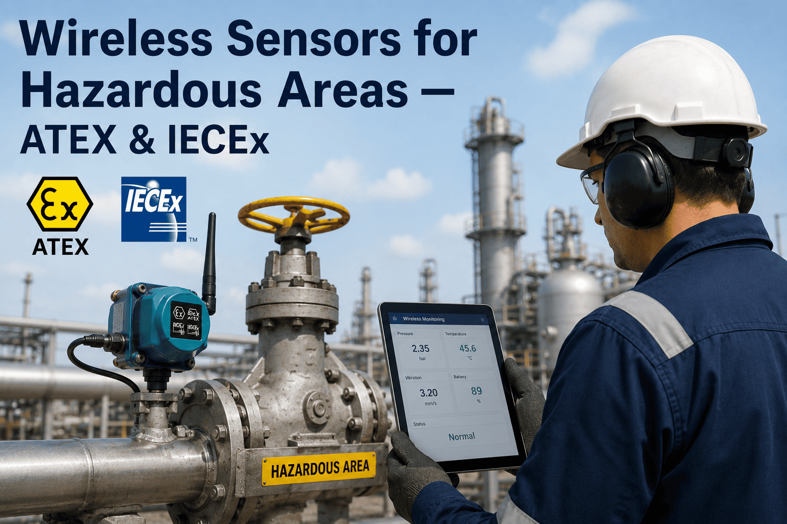
Once the area classification is defined, the next engineering decision is selecting electrical and mechanical equipment with the appropriate level of protection. The IEC system uses Equipment Protection Levels, which are defined by the likelihood of the equipment becoming a source of ignition. EPL Ga is the highest level, required in Zone 0, indicating the equipment provides a very high level of protection even during rare fault conditions. EPL Gb is required in Zone 1, providing a high level of protection during normal operation and expected fault conditions. EPL Gc is required in Zone 2, providing an increased level of protection during normal operation, with no requirement to withstand expected faults because faults are themselves unlikely in a Zone 2 environment.
Each Equipment Protection Level can be achieved through multiple protection concepts, which are the specific design techniques used to prevent ignition. The selection of which protection concept to use is driven by a combination of the zone requirement, the type of equipment, the voltage and power level, and practical considerations like maintenance access and cost. Understanding the mapping between zones, EPLs, and protection concepts is essential because specifying the wrong protection concept for a given zone is a compliance failure, even if the equipment carries a valid certification mark.
| Zone | Required EPL | Applicable Protection Concepts | Common Equipment Examples |
|---|---|---|---|
| Zone 0 | EPL Ga | Ex ia (Intrinsic Safety), Ex s (Special) | Instrumentation transmitters, gas detectors, associated apparatus with energy limitation |
| Zone 1 | EPL Gb | Ex ia, Ex d (Flameproof), Ex e (Increased Safety), Ex q (Sand), Ex m (Encapsulation), Ex p (Pressurization) | Motor control centers, lighting fixtures, junction boxes, electric motors, analyzers |
| Zone 2 | EPL Gc | Ex nA (Non-sparking), Ex nC (Protected), Ex nR (Restricted breathing), Ex nL (Limited energy), plus all Zone 1 concepts | General purpose motors with non-sparking features, standard enclosures with restricted breathing, lighting |
Temperature classification is a parallel requirement that applies independently of the zone and the protection concept. Every piece of electrical equipment installed in a hazardous area must have a T-class rating that indicates the maximum surface temperature it will reach under fault conditions. This T-class must be lower than the auto-ignition temperature of the specific flammable gas or vapor present in that area. Specifying a T6 rated piece of equipment in an area where T3 would be sufficient is safe but may add cost and limit supplier options. Specifying T3 equipment in an area where the gas requires T6 is a critical safety failure that could allow a hot surface to ignite the atmosphere even if the equipment perfectly prevents sparking. The T-class requirement is determined by the fluid characterization step of the area classification process and must be documented on the area classification drawing alongside the zone boundary.
Why drawings drift from reality and what happens when they do
An area classification drawing is a snapshot of the engineering team's understanding of the facility at a specific point in time. From the day the drawing is issued, the facility begins to change in ways that the drawing does not automatically reflect. New sample points are added to satisfy a process monitoring requirement. A vent that was originally directed upward is modified to discharge horizontally to avoid a walkway. A temporary repair clamp is left in place permanently. A new cable tray is routed through an area that was classified as safe on the original drawing but is now adjacent to a re-routed pipeline carrying a heavier gas. Each of these changes has the potential to alter the area classification, and almost none of them trigger a formal revision to the classification drawing.
The result is a growing divergence between the documented classification and the actual field conditions. This divergence creates two distinct risk patterns. In the first pattern, the field has become more hazardous than the drawing indicates, meaning equipment is installed in an area that is now effectively Zone 1 or Zone 2 but is not recognized as such on the drawing. The equipment may be standard industrial grade without any explosion protection, and because the drawing says the area is safe, maintenance technicians do not take the precautions they would take in a classified area. This is the most dangerous form of classification drift because it creates a false sense of security around equipment that is actively at risk of igniting a flammable atmosphere.
Field is more hazardous than the drawing
New release sources, changed venting, or modified processes have created a Zone 1 or Zone 2 condition in an area the drawing shows as unclassified. Standard equipment is exposed to flammable atmospheres without the protection the engineering team believed was in place. Maintenance activities proceed without hazardous area permits.
Field is less hazardous than the drawing
Process changes, improved sealing, or added ventilation have reduced the hazard, but the drawing still shows a classified zone. The facility continues to purchase and install expensive Ex equipment for an area that no longer requires it. Capital and maintenance budgets absorb unnecessary costs for the life of the facility.
In the second pattern, the field has become less hazardous than the drawing indicates, perhaps because a source of release was permanently eliminated or because mechanical ventilation was added to an area that originally relied on natural ventilation. The risk in this pattern is purely financial, as the facility continues to specify and install expensive explosion-proof equipment in areas that could safely use standard industrial equipment. While this does not create a safety hazard, it represents a significant and ongoing waste of capital that could be redirected to genuine risk reduction activities. Both patterns are symptoms of the same underlying problem: the area classification drawing is treated as a one-time engineering deliverable rather than a living document that must be maintained and verified against field conditions throughout the operating life of the facility.
Turning static drawings into a living compliance framework
Converting area classification from a static PDF drawing into a digital, data-linked model changes how the facility manages hazardous area risk on a daily basis. Instead of relying on engineers and operators to remember that a particular area is Zone 1, the classification data is embedded in the digital systems that drive daily work processes. When a maintenance technician scans a piece of equipment in the field, the system immediately indicates whether that equipment is located within a classified zone, what the zone classification is, what temperature class is required, and what permits are needed to perform work on that equipment. This eliminates the reliance on memory and paper drawings that may be outdated.
For capital projects and modifications, a digital classification model provides an immediate impact assessment capability. When a process engineer proposes adding a new vent or rerouting a pipeline, the digital system can overlay the proposed change on the existing classification boundaries and flag any locations where new equipment or modified release sources would change the zone classification. This allows the engineering team to evaluate classification impacts during the design phase, when changes are inexpensive, rather than discovering them during a pre-startup safety review, when changes are costly and schedule-disruptive. The digital model also creates an audit trail that documents why each zone boundary exists, what assumptions were made about ventilation and release rates, and when the classification was last verified against field conditions.
Field Verification Integration
Link area classification data to field inspection routines so zone boundaries are periodically verified against actual equipment locations, release sources, and ventilation conditions during walkthroughs.
Permit-to-Work Automation
Automatically trigger hazardous area work permit requirements when maintenance or construction activities are scheduled in classified zones, removing manual permit determination from the workflow.
Equipment Compliance Tracking
Verify that every piece of equipment installed in a classified zone carries the correct Ex certification, protection concept, and temperature class for the zone it occupies.
Management of Change Triggers
Flag when a proposed process modification, new equipment installation, or ventilation change alters the assumptions underlying an existing area classification boundary.
The transition from paper-based classification management to a digital framework does not require the facility to redo its entire area classification study. It begins by importing the existing approved classification drawings and equipment data into the digital platform, creating a baseline that matches the current documentation. From that baseline, the facility can then prioritize field verification activities in the areas where classification accuracy matters most, typically where Zone 0 and Zone 1 areas border unclassified areas, and where the consequences of an undetected classification error would be most severe. This risk-based approach to digital conversion allows the facility to realize immediate safety benefits in the highest-priority areas while building toward comprehensive coverage over time.
Area classification and explosion protection, explained plainly
Stop relying on outdated area classification drawings
iFactory digitizes your Zone 0, 1, and 2 boundaries, links them to live equipment data, and triggers alerts when field changes put your explosion protection compliance at risk.