Turnaround logistics in oil and gas facilities move more tonnage in two weeks than the plant handles in six months of normal operations, yet the site layout, crane positioning, and material staging plans that make this possible are often drafted on a whiteboard three weeks before the shutdown. A poorly planned laydown area creates bottlenecks that cascade into crane waiting time, crew idle hours, and schedule delays that no amount of execution effort can recover. Plants that treat logistics as a dedicated planning workstream with its own engineering deliverables, timelines, and readiness gates consistently start their turnarounds faster and maintain higher productivity throughout the execution window. Logistics planners ready to replace whiteboard sketches with a coordinated digital site plan can book a demo to see how spatial planning integrates with work package tracking.
TURNAROUND LOGISTICS · LAYDOWN & CRANE PLANNING · OIL & GAS
TAR Logistics: Laydown Areas, Crane Plans & Rigging Execution
The physical movement of materials, equipment, and crews across a turnaround site is the backbone of execution. This is the engineering framework for planning it correctly.
The Hidden Cost of Poor Turnaround Logistics
30-40%
Of first-shift delays traced back to material not being in the correct laydown location when crews arrive
$8-15K
Cost per hour of crane standby time when lift schedules are not coordinated with work package sequencing
2.5x
More vehicle movement during a turnaround compared to normal operations, overwhelming unmanaged traffic plans
18%
Average reduction in crew productivity when temporary facilities are positioned too far from the work zones
Laydown Area Zoning Framework
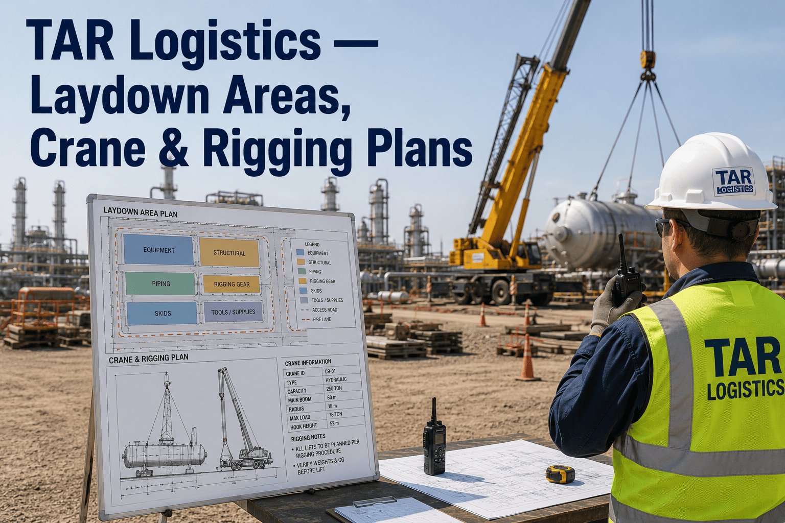
A turnaround laydown area is not a single open yard where materials are dumped and crews search for what they need. It is a zoned logistics system where every square meter is assigned a purpose, every material kit has a designated position, and every movement path between the laydown and the work front is planned in advance. The zoning framework below represents the standard layout that high-performing plants use to eliminate search time and prevent congestion during peak execution periods.
Zone A: Receiving & Inspection
Materials arrive from procurement and suppliers, are unloaded, counted against the shipping manifest, and undergo incoming inspection. This zone must be adjacent to the plant access road and have overhead coverage for weather protection during inspection. No material stays in this zone longer than forty-eight hours before being moved to its assigned staging position.
Zone B: Work Package Staging
Materials are organized by work package and unit area, with each kit tagged with the work package number, equipment tag, and intended installation location. This zone is the primary pick point for field crews, and its layout must mirror the physical layout of the unit so that crews can intuitively find their materials based on where they are working in the plant.
Zone C: Heavy Equipment & Modules
Heat exchangers, vessels, compressor rotors, and prefabricated modules that require crane lifts are positioned in this zone with dedicated crane access and sufficient clear radius for rigging. Each item is placed on blocking with lift lugs accessible, and the rigging plan for each lift is posted at the staging position so the rigging crew can verify configurations before the crane arrives.
Zone D: Removed Equipment & Scrap
Equipment removed from the unit during the turnaround is staged here for inspection, repair decision, or scrap disposition. This zone must be kept separate from the receiving and staging zones to prevent removed items from being confused with new materials. A clear disposition pathway must be established so that items move out of this zone within seventy-two hours to prevent congestion buildup as the turnaround progresses.
Zone E: Scaffold & Temporary Services
Scaffold materials, temporary lighting, temporary power distribution, welding machines, and gas cylinder racks are staged in this zone. It must be positioned to allow scaffold trucks and service vehicles to load and depart without crossing pedestrian routes or interfering with crane swing paths. Gas cylinder storage in this zone must comply with facility separation distance requirements.
Zone F: Contractor Staging & Welfare
Contractor break areas, tool cribs, PPE distribution points, and first aid stations are located in this zone. It must be positioned at the perimeter of the laydown area with clear pedestrian routes to the unit entry points. The distance from this zone to the farthest work front should not exceed four hundred meters on foot to limit transit time during shift changes and break periods.
Crane Planning & Lift Classification Matrix
Crane logistics during a turnaround require a level of planning that goes far beyond calling a crane rental company and ordering a machine by capacity. Every lift must be classified, every crane position must be engineered, and every lift sequence must be coordinated with the work package schedule to prevent crane conflicts and standby delays. The following matrix classifies lifts by complexity and maps each classification to its required planning deliverable.
| Lift Class |
Weight Range |
Planning Requirement |
Approval Authority |
| Routine |
Under 5 tonnes |
Standard lift plan template, pre-approved rigging configurations |
Site lift supervisor signoff on the day of the lift |
| Standard |
5 to 25 tonnes |
Detailed lift plan with crane selection, ground bearing calculation, and swing radius plot |
Turnaround lift coordinator review and approval minimum 48 hours before the lift |
| Critical |
25 to 100 tonnes |
Engineered lift study with independent review, ground bearing survey, and tandem lift procedures if applicable |
Third-party lift engineer review and plant management authorization |
| Super Critical |
Over 100 tonnes |
Full engineering study with finite element analysis of rigging, soil bearing report, wind speed monitoring plan, and contingency lift procedure |
Corporate engineering review with third-party verification and insurance notification |
TURNAROUND LOGISTICS · SITE PLANNING · OIL & GAS
Map Your Turnaround Logistics Before the First Truck Arrives
See how digital laydown zoning, crane scheduling, and material positioning eliminate the logistics chaos that derails first-shift productivity.
Rigging Plan Components That Must Be Engineered
Rigging plans are frequently treated as an afterthought that the rigging crew figures out on the day of the lift, but this approach is responsible for a disproportionate share of logistics delays and safety incidents during turnarounds. Every rigging plan for a standard or higher classification lift must include the following engineered components, and each component must be verified by a qualified person before the lift is authorized to proceed.
01
Load Weight & Center of Gravity
The lifted item must have a verified weight that includes all attached components, residual fluid, and rigging hardware. The center of gravity must be calculated or determined from the manufacturer drawing. Lifting an item with an unknown or assumed center of gravity is the single most common cause of load instability during turnaround lifts, and it is entirely preventable with proper engineering documentation before the lift is scheduled.
02
Sling Configuration & Angle Calculation
The sling type, size, and configuration must be specified with calculated sling angles at the rigged condition. Sling angle derating must be applied when the angle between the sling and the horizontal is less than sixty degrees. The rigging plan must show the rigged geometry with actual angles so the rigging crew can verify in the field that the as-rigged condition matches the engineered plan before the crane takes the load.
03
Crane Capacity & Load Chart Verification
The selected crane must have sufficient capacity at the required radius, boom length, and boom angle for the lifted weight including all rigging, spreader bars, and hooks. The load chart used for verification must be the specific chart for the crane model and configuration being used, including deductions for boom extension, sheave blocks, and any anti-two-block devices. Using a generic capacity number without referencing the actual load chart at the rigged radius is a planning failure.
04
Ground Bearing Pressure & Crane Matting
The ground bearing pressure under the crane outriggers or tracks must be calculated and compared against the verified soil bearing capacity at the specific crane position. If the bearing pressure exceeds the soil capacity, engineered matting or cribbing must be specified with sufficient size and thickness to distribute the load below the soil bearing limit. Ground bearing failures during turnaround lifts are rare but catastrophic when they occur, and they are always traceable to this calculation being skipped.
05
Swing Radius & Obstacle Clearance
The crane swing path must be plotted on the site plan showing all obstacles within the swing radius including structures, piping, scaffold, overhead power lines, and other cranes. Minimum clearance distances must be maintained per facility standards and regulatory requirements. When multiple cranes are operating in adjacent areas, the swing radius plots must be overlaid to identify conflict zones where simultaneous operation is prohibited.
06
Weather Hold Criteria & Contingency
The lift plan must specify the maximum wind speed at which the lift can proceed, based on the load surface area, boom length, and crane manufacturer limits. A wind monitoring procedure must be in place for critical and super critical lifts with a defined stop-work trigger. The contingency plan must address what happens if the lift is suspended at mid-swing due to wind, including whether the load can be safely lowered or must be held in position until conditions improve.
Temporary Facilities & Services Layout
Temporary facilities during a turnaround are not optional conveniences but operational infrastructure that directly affects crew productivity and safety. The positioning, capacity, and readiness of each temporary service must be planned as part of the logistics workstream, not delegated to individual contractors to arrange on their own. The following grid maps each temporary facility category to its planning requirement and the consequence of getting the layout wrong.
Temporary Lighting
LED tower lights positioned at each major work area with coverage overlap to eliminate shadow zones. Planning must account for scaffold obstruction and equipment blocking. Wrong layout creates dark spots at vessel internals and elevated platforms where confined space work is happening.
Temporary Power
Distribution panels with dedicated circuits for welding, tool power, and lighting to prevent tripping from overloaded shared circuits. Cable routing must avoid vehicle paths and crane swing areas. Wrong layout causes repeated power outages that stop welding work mid-pass and damage equipment.
Welding Gas & Supply
Manifold stations with argon, oxygen, and fuel gas positioned within fifty meters of the welding work fronts. Hose runs longer than fifty meters create pressure drop problems and trip hazards. Wrong layout forces welders to run long hoses that kink and cause weld quality issues.
Hydrotest Water Supply
Temporary water headers with connection points at each equipment location requiring hydrotesting. Flow rate and pressure must be sufficient for simultaneous testing of multiple circuits. Wrong layout requires long hose runs that delay test cycles and consume schedule time.
Nitrogen Supply
Liquid nitrogen vaporizers with sufficient capacity to support purging, blanketing, and catalyst drying operations simultaneously. Temporary piping must be sized for the required flow rate. Wrong layout causes pressure drops that extend purge cycles and delay equipment opening for mechanical work.
Sanitation & Welfare
Toilet facilities, hand wash stations, and drinking water positioned within one hundred meters of every work zone. Crews walking more than one hundred meters for a break cycle lose fifteen to twenty minutes per break in transit time. Wrong layout compounds into significant productivity loss across a two-week turnaround.
Traffic Management During Peak Execution
Vehicle and pedestrian traffic during a turnaround operates at a volume that the plant road network was never designed to handle. Without a managed traffic plan, delivery trucks, crane transporters, scaffold trucks, and pedestrian crews create conflicts that cause delays, near-misses, and occasional incidents. The comparison below shows the difference between a managed and unmanaged traffic environment during peak turnaround execution.
Managed Traffic Plan
One-way traffic loops with designated entry and exit points eliminate head-on conflicts on narrow plant roads
Pedestrian corridors separated from vehicle routes with physical barriers at high-traffic crossing points
Delivery windows assigned by material category to prevent all suppliers arriving simultaneously at the gate
Crane transport routes pre-cleared with all obstructions removed and temporary road plates installed over trenches
Traffic marshals posted at choke points during shift change to prevent pedestrian and vehicle conflicts
Unmanaged Traffic
Two-way traffic on narrow roads creates gridlock when trucks meet and neither can reverse safely
Pedestrians walk on roadways alongside moving trucks because no separate routes were established
Delivery trucks queue at the gate and block the access road for emergency vehicles and crane transporters
Crane transporters encounter unexpected obstructions and must stop to clear the route, burning mobilization time
Near-miss incidents between crews and vehicles increase during shift changes when traffic volume peaks
Logistics Readiness Timeline by Deliverable
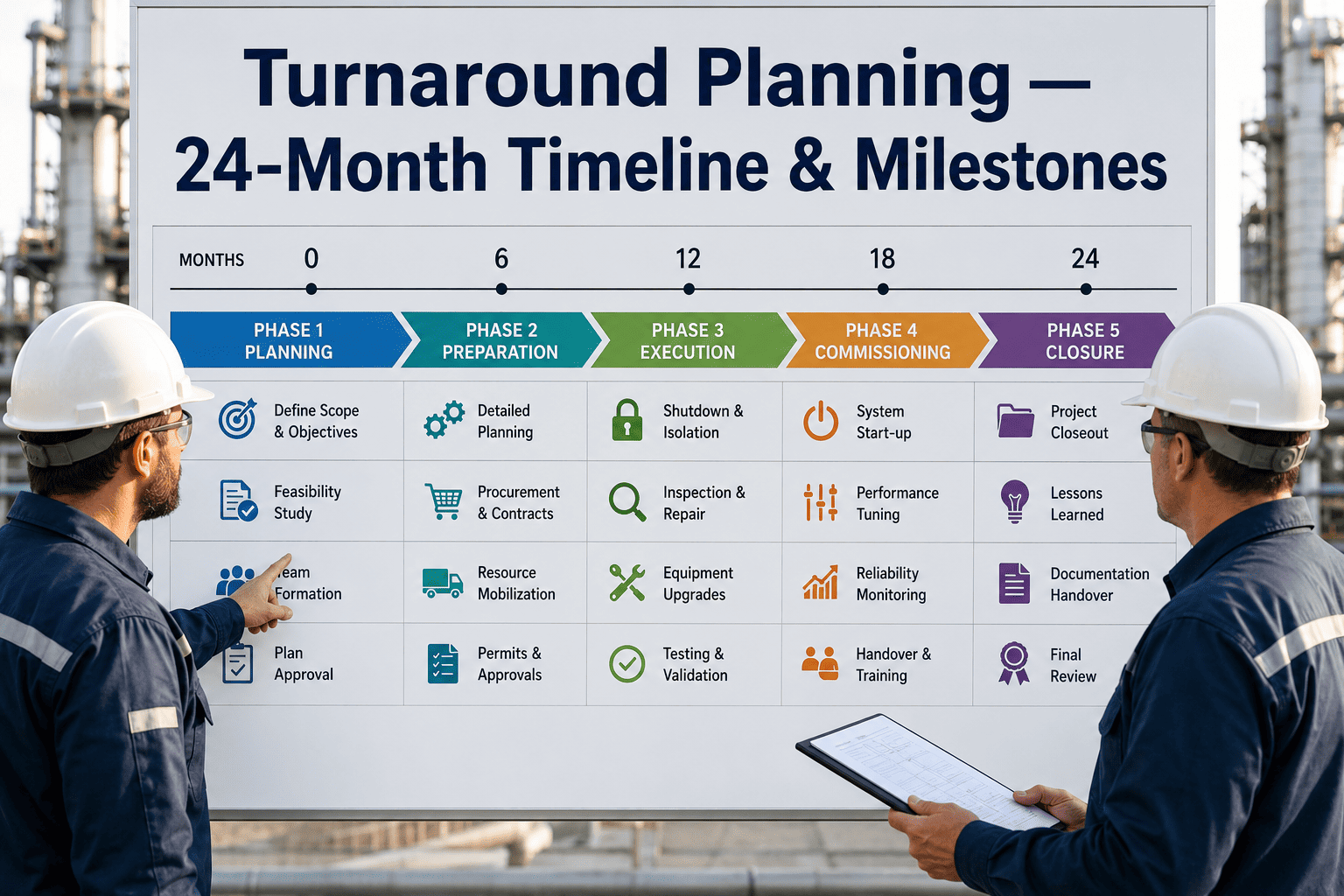
Logistics deliverables have longer lead times than most turnaround planners account for. Crane pad construction, temporary road installation, and laydown area preparation cannot be completed in the final week before shutdown. The following timeline maps each logistics deliverable to its required start date relative to the shutdown, ensuring that the site is physically ready before the first contractor crew arrives.
| Logistics Deliverable |
Start Date |
Completion Date |
Owner |
| Laydown area survey and grading |
T-12 weeks |
T-8 weeks |
Site logistics coordinator |
| Temporary road construction and drainage |
T-10 weeks |
T-6 weeks |
Civil contractor |
| Crane pad construction and soil verification |
T-8 weeks |
T-4 weeks |
Geotechnical and civil teams |
| Temporary power and lighting installation |
T-6 weeks |
T-2 weeks |
Electrical contractor |
| Temporary facilities and welfare setup |
T-4 weeks |
T-1 week |
Site services coordinator |
| Laydown zone marking and signage |
T-3 weeks |
T-1 week |
Logistics coordinator |
| Traffic management plan deployment |
T-2 weeks |
T-2 days |
Security and logistics |
| Crane mobilization and positioning |
T-1 week |
T-1 day |
Lift coordinator |
| Material receiving and zone B staging |
T-3 weeks |
T-1 day |
Material coordinator |
| Final logistics readiness walkthrough |
T-2 days |
T-1 day |
Turnaround manager |
Logistics Failures That Derail Turnaround Schedules
Post-turnaround reviews consistently identify the same logistics failure patterns across different plants and different turnaround scopes. These are not random events but predictable consequences of treating logistics as a secondary concern rather than an engineering discipline. Each failure pattern below has been documented in multiple turnaround post-mortems and represents a risk that can be eliminated through proper planning.
Laydown Congestion Spiral
Materials arrive faster than they are consumed and the laydown area fills beyond its planned capacity. New deliveries are stacked on top of earlier deliveries, work package kits become buried and unfindable, and crews spend increasing amounts of time searching for materials as the turnaround progresses. This spiral is nearly impossible to reverse once it starts because the congestion prevents the removal trucks from accessing the scrap and return zones.
Crane Conflict Cascades
Two cranes are scheduled for lifts in adjacent areas at overlapping times, and neither lift coordinator was aware of the other because the lift schedule was maintained in separate spreadsheets. When the conflict is discovered, one crane goes on standby while the other completes its lift sequence. The standby cost is visible, but the hidden cost is the work package that was scheduled to use that crane slot and now has no lift window available for the next forty-eight hours.
Temporary Service Overload
Temporary power circuits are shared across too many welding stations without proper load balancing. When multiple welders strike arcs simultaneously, the distribution panel trips and all connected work stops. The electrician resets the panel, work resumes, and the cycle repeats. Each trip costs five to fifteen minutes of lost welding time, and across a two-week turnaround with dozens of welders, the cumulative impact is measured in days of lost schedule.
Pedestrian-Vehicle Conflict Points
No physical separation was established between pedestrian routes from the welfare area and vehicle routes to the laydown yards. During shift changes, crews walking to and from the unit share the road with delivery trucks and scaffold transports. Near-miss reports accumulate but are treated as individual incidents rather than a systemic planning gap until an injury occurs and the investigation traces it back to the traffic plan that was never implemented.
Logistics Coordinators Ask
How much laydown area do we actually need for a turnaround?
The required laydown area depends on the total volume of materials and equipment being staged, but a practical starting point is one and a half to two square meters per tonne of material for the peak staging period. This must be calculated by summing the footprint of every work package material kit, every heavy equipment item, and every temporary facility, then adding twenty percent buffer for access aisles and maneuvering space. Plants that estimate laydown area by visual guess rather than calculated footprint consistently end up with congestion problems by the middle of the first week. Teams can
book a demo to see how digital material tracking calculates laydown requirements from work package data.
Should we own our cranes or rent them for each turnaround?
The decision depends on turnaround frequency and the consistency of lift requirements across events. Plants with turnarounds every eighteen to twenty-four months that require similar crane configurations each time often find that owning one or two base-capacity cranes and renting supplemental capacity for peak lift periods is more cost-effective than full rental. Plants with less predictable turnaround schedules or highly variable lift requirements are usually better served by rental, since owned cranes sitting idle between turnarounds carry significant maintenance and certification costs. The logistics planning tool should track crane utilization rates across events to inform this decision with actual data rather than assumptions.
How do we coordinate multiple cranes operating in the same area?
Multiple crane coordination requires a single integrated lift schedule that shows every planned lift across all cranes with time windows, boom positions, and swing radius plots overlaid on a single site plan. The lift coordinator must have visibility across all crane operations and the authority to reschedule lifts when conflicts are identified. When each crane operates from its own schedule maintained by its own contractor, conflicts are inevitable because no single person has the complete picture. Digital lift scheduling tools that consolidate all crane operations into a single view with automated conflict detection are the most reliable way to prevent these situations, and they are significantly more effective than manual coordination meetings.
What is the biggest mistake plants make with temporary power during turnarounds?
The most common and most expensive mistake is undersizing the temporary power distribution by estimating total demand and dividing by the number of circuits without accounting for the simultaneous use factor. Not every welding station will be drawing full amperage at the same time, but the peak demand during shift start when all welders strike their first arcs simultaneously can be significantly higher than the average demand calculated from total weld hours. The distribution system must be sized for this peak simultaneous demand, not the average, and individual circuit breakers must be rated to prevent a single fault from tripping an entire panel that serves multiple work fronts.
How does digital logistics tracking integrate with the turnaround schedule?
Digital logistics tracking connects laydown positions, crane schedules, and material status directly to the work packages on the critical path. When a work package is scheduled to start, the system confirms that its material kit is staged in the correct laydown position, the required crane slot is reserved, and the temporary services at the work location are verified operational. If any of these logistics prerequisites are not met, the system flags the work package as logistics-blocked before the crew is dispatched, allowing the logistics coordinator to resolve the issue proactively. This integration eliminates the pattern of crews arriving at work locations to find materials missing or cranes not available, which is the most common first-shift delay mechanism in turnarounds that lack digital logistics coordination. Contact
support to understand how this integration works with existing scheduling tools.
TURNAROUND LOGISTICS · CRANE PLANNING · LAYDOWN MANAGEMENT
Your Next Turnaround Site Should Not Be Planned on a Whiteboard
See how digital laydown zoning, lift scheduling, and logistics readiness tracking replace guesswork with engineered site plans.