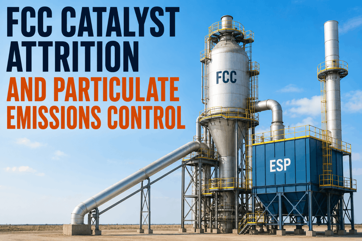
In a fluid catalytic cracking unit, catalyst is simultaneously the most expensive consumable and the most consequential emissions source — and the two problems are directly linked. Fresh FCC catalyst costs $3,000 to $4,000 per short ton, and catalyst losses in a unit running at poor attrition control can reach levels that represent $2 to $4 million in annual makeup cost before the stack opacity violation arrives at the door. By the time the regenerator flue gas is triggering particulate exceedances at the continuous emissions monitoring system, the mechanical and operational conditions that caused the loss have typically been degrading for weeks. Cyclone efficiency has been eroding, the 0-to-40 micron fraction in the equilibrium catalyst inventory has been declining, and the Davison Attrition Index of fresh catalyst additions has not been benchmarked against the unit's current operating severity. iFactory AI integrates FCC unit process data — Ecat particle size distribution, fresh catalyst DI and ABD, regenerator cyclone differential pressures, ESP or third-stage separator performance, and stack opacity readings — into a single continuous monitoring environment that connects catalyst attrition management to emissions compliance, unit reliability, and economic performance simultaneously. To see how iFactory closes the attrition-to-emissions visibility gap in your FCC unit, Book a Demo with our refinery process team.
Why FCC Catalyst Loss Is a Refinery-Wide Economic and Compliance Event
The Full Cost Chain From Attrition to Stack Violation
High catalyst losses in an FCC unit are rarely a single-cause failure — they are a convergence of catalyst physical properties, unit operating severity, mechanical integrity of the cyclone system, and the adequacy of downstream particulate abatement equipment. Each element contributes, and each requires its own monitoring framework to manage. What makes the problem particularly difficult to manage without integrated analytics is that the leading indicators of increasing catalyst loss — shifts in Ecat particle size distribution, declining 0-to-40 micron content, rising cyclone differential pressure trends — are measured and reviewed by different teams on different schedules, and are never automatically connected to the stack opacity readings that signal the regulatory exposure. The table below maps the primary failure pathways that drive FCC catalyst attrition and emissions exceedances in U.S. refinery operations.
| Failure Pathway | Primary Indicator | Operational Consequence | Emissions Impact | Annual Cost Exposure |
|---|---|---|---|---|
| High Fresh Catalyst DI | DI >12 in fresh catalyst additions | Accelerated microfine generation in riser and regenerator | Rising 0–40 μm fraction, increased stack opacity | $400K – $900K |
| Regenerator Cyclone Degradation | Declining dP across primary or secondary cyclones | Reduced separation efficiency, catalyst loss to plenum and flue gas train | Direct stack opacity violation risk | $600K – $1.8M |
| ESP Underperformance | Declining collection efficiency, rising outlet PM | Catalyst fines bypass to atmosphere; erosion of downstream equipment | MACT II / NSPS exceedance, opacity violation | $300K – $1.2M |
| Low Ecat ABD / Coarse Shift | ABD decline or mean particle size increase in Ecat | Reduced cyclone capture efficiency; deteriorating fluidization | Increased carryover to third-stage separator and ESP | $200K – $600K |
| Erratic Catalyst Circulation | Slugging flow in standpipes, pressure balance instability | Afterburn increase, yield deterioration, mechanical wear escalation | Burst particulate events during circulation upsets | $500K – $1.5M |
The Three Measurement Systems That Determine Attrition Management Quality
DI, ABD, and Ecat PSD: What Each Metric Tells You and How iFactory Connects Them
Effective FCC catalyst attrition management requires three distinct measurement systems to be operated correctly and their outputs correlated against each other and against emissions data — a correlation that manual review processes almost never achieve consistently. iFactory's FCC analytics platform automates this correlation continuously, connecting the catalyst characterization lab data, unit process measurements, and emissions monitoring readings into a single performance picture updated with every data input. Book a Demo to see the catalyst attrition monitoring dashboard.
Cyclone and ESP Performance: The Mechanical Abatement Chain
Internal Cyclones, Third-Stage Separators, and Electrostatic Precipitators as an Integrated System
The particulate abatement chain in an FCC regenerator operates as a series of staged separation systems — internal primary and secondary cyclones, an external third-stage separator (TSS) or third-stage cyclone battery, and in many U.S. refineries, an electrostatic precipitator or wet scrubber as the final stage before the stack. Each stage is effective within a specific particle size range, and the failure of any one stage transfers its carryover load to the next — ultimately reaching the stack at concentrations that may exceed EPA MACT II limits. Book a Demo to see the ESP and cyclone performance monitoring module.
iFactory FCC Attrition Analytics: Connecting Catalyst Data to Compliance Outcomes
From Isolated Lab Results to Integrated Unit Intelligence
The operational gap that iFactory addresses in FCC attrition management is not a measurement gap — U.S. refineries are already measuring DI, ABD, and Ecat PSD as part of routine operations. The gap is an integration and speed gap: lab results are reviewed in batch, not correlated automatically with process data, and the emissions consequences of deteriorating attrition control are only visible at the stack — after the damage is done. iFactory's FCC analytics platform closes this gap by connecting every data stream in the attrition-to-emissions chain into a single monitoring environment with continuous correlation and automated alerting.
- DI and ABD reviewed monthly — deterioration identified weeks after emissions impact begins
- Ecat PSD trends analyzed in isolation from unit operating conditions and cyclone performance
- Cyclone dP reviewed manually at shift — stage-by-stage degradation not correlated to carryover loading
- ESP performance assessed at quarterly compliance testing — underperformance invisible between tests
- Stack opacity exceedances investigated reactively — root cause analysis after the regulatory event
- Catalyst addition decisions based on activity targets alone — no attrition risk weighting for current unit conditions
- DI and ABD correlated with Ecat PSD shifts automatically — attrition trends flagged within days of onset
- PSD mass balance model continuously updated — fines surplus vs. deficit calculated in real time
- Stage-by-stage cyclone dP analysis separates primary, secondary, and TSS failure modes automatically
- ESP secondary voltage, current, and spark rate monitored continuously against opacity targets
- Stack opacity exceedance root cause analysis delivered within minutes using multi-variable correlation
- Catalyst addition DI tracking provides emissions risk advisory for each planned addition event
Conclusion: FCC Catalyst Attrition Control Is a Real-Time Analytics Problem
The economic and regulatory stakes in FCC catalyst attrition management are high enough that the standard monthly lab review and quarterly compliance testing cycle is simply not sufficient to manage the risk. Catalyst at $3,500 per ton leaving through the stack at elevated rates, regulatory opacity limits with enforcement consequences, and mechanical wear in the flue gas train from increased catalyst loading are all outcomes of the same underlying problem: the data that would enable earlier intervention exists, but it is not being integrated and analyzed at the speed and resolution that the problem requires.
iFactory AI's FCC attrition analytics platform brings continuous correlation of catalyst characterization data, unit process measurements, and emissions monitoring readings into a single operating environment — giving FCC process engineers and reliability teams the early warning system that converts reactive emissions management into proactive attrition control. The data is already being generated. iFactory provides the integration layer that makes it actionable before the stack opacity exceedance, not after it.
Frequently Asked Questions
DI measures the rate of sub-20-micron fines generation under a standardized jet cup test — a DI below 12 is the accepted industry benchmark for acceptable attrition resistance. Fresh catalyst additions with higher DI values generate disproportionate microfines that bypass cyclone separation and drive stack opacity exceedances.
A declining 0-to-40 micron fraction in the Ecat inventory means fines are being lost from the system faster than they are being generated — indicating cyclone or separator bypass that is sending fine particles directly to the stack rather than retaining them in the circulating inventory.
The EPA NSPS and MACT II Refinery standard sets a particulate limit of 1.0 lb per 1,000 lbs of coke burn-off for FCCU regenerator flue gas — with many state and local air districts (such as California's BAAQMD) imposing additional or more stringent opacity and PM limits.
iFactory correlates the timing and magnitude of Ecat PSD shifts against fresh catalyst DI addition data and cyclone dP trends simultaneously — if fines loss tracks DI addition events it signals chemistry; if it tracks cyclone dP decline regardless of additions, it signals mechanical degradation.
iFactory integrates with the FCC unit's Level 2 process historian (DCS data for cyclone dP, ESP power, and throughput), LIMS for Ecat PSD and fresh catalyst characterization data, and the CEMS system for stack opacity and PM readings — with integration typically completed within two weeks.