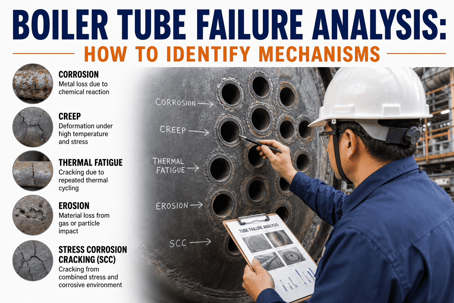
Boiler tube failures force more unplanned shutdowns than any other single cause in fossil and industrial steam systems. Most plants react to a leak, patch the tube, and restart without ever identifying the root mechanism, which means the same failure pattern repeats on the next outage cycle. The difference between a one-time repair and a recurring problem is whether your team can read the damage morphology correctly the first time. Understanding which mechanism caused the failure changes the entire corrective action path from guesswork to targeted action. See how iFactory structures this analysis workflow by visiting iFactory support.
Boiler Reliability · Failure Analysis
Read the Damage, Name the Mechanism, Stop the Repeat Failure
Every tube rupture leaves a visible signature. Learning to read failure morphology correctly is the fastest way to move from reactive patching to root-cause elimination in your boiler systems.
40-50%
Of all forced boiler outages in fossil plants are caused by tube failures, making it the single largest source of unplanned downtime across the fleet
70%
Of tube failures are repeat events because the root mechanism was never properly identified during the initial repair and restart cycle
6
Primary failure mechanisms account for the vast majority of all boiler tube damage across industries, fuel types, and boiler designs
$500K+
Average cost per major tube failure event when you include lost generation, emergency repair labor, replacement materials, and secondary damage
Identification Process
Five Steps From Rupture to Root Cause
Failure mechanism identification is not guesswork. It follows a structured sequence where each step narrows the candidate list until one mechanism fits all the evidence.
1
Locate the Failure
Pinpoint exact tube, elevation, orientation, and circuit position before anything is moved or cut from the boiler
2
Examine Morphology
Observe rupture shape, edge thickness, surface condition, and whether the damage is on the fireside or waterside
3
Measure Thickness
Compare remaining wall to design thickness at the failure site and at intervals away from the damaged area
4
Review Conditions
Cross-reference findings with temperature logs, water chemistry records, load history, and recent startup or shutdown events
5
Name the Mechanism
Match the combined visual, dimensional, and operational evidence to a known failure signature with confidence
Failure Mechanisms
Six Mechanisms Behind Nearly Every Boiler Tube Failure
Each mechanism produces a distinct damage pattern. Recognizing these patterns on the plant floor is what separates a correct diagnosis from a misidentification that guarantees a repeat failure.
Short-Term Overheating
SignatureBulge with thin knife-edge rupture
DurationMinutes to hours
LocationAny circuit with flow loss
TriggerBlockage, low water, pump trip
Long-Term Overheating
SignatureLongitudinal rupture with thick lips
DurationThousands of operating hours
LocationHigh-temperature sections
TriggerSustained operation above design temp
Flow Accelerated Corrosion
SignatureSmooth thinning, no oxide scale
DurationMonths to years
LocationBends, elbows, two-phase regions
TriggerWater chemistry, velocity, oxygen
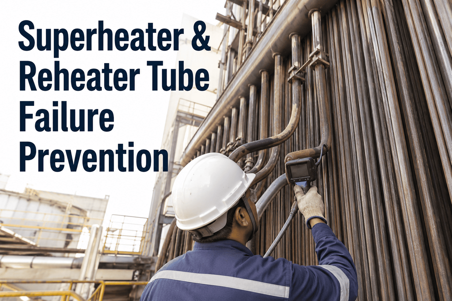
Fireside Corrosion
SignatureExternal wall loss with ash deposits
DurationMonths to years
LocationSuperheaters, reheaters
TriggerSulfur, chlorine, alkali in fuel
Stress Corrosion Cracking
SignatureIntergranular crack networks
DurationWeeks to months
LocationWelds, bends, crevices
TriggerCaustic environment plus tensile stress
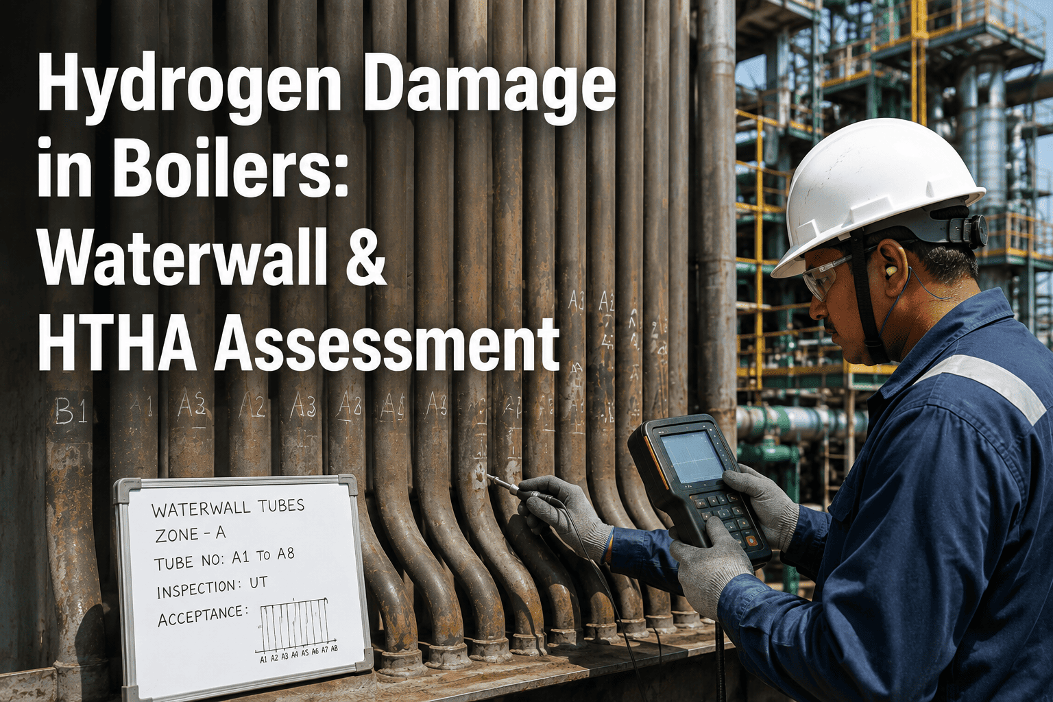
Hydrogen Damage
SignatureDecarburization and microcracking
DurationWeeks to months
LocationWaterside, acidic zones
TriggerHydrogen from corrosion diffusion
Quick Reference
Morphology Comparison Across All Six Mechanisms
Use this matrix to compare what you observe on the failed tube against the expected indicators for each mechanism. No single row confirms a diagnosis, but the combined pattern across all rows points to one answer.
Investigation Protocol
Eight-Step Field Investigation Checklist
Following a consistent sequence at every tube failure ensures no evidence is lost and no step is skipped. Each item below feeds directly into the mechanism identification process.
1
Document Failure Location
Record exact elevation, tube orientation, circuit ID, and proximity to burners or headers before anything is moved or cut from the boiler
2
Photograph Before Cutting
Capture the as-found condition including deposits, discoloration, and condition of adjacent tubes for visual reference during analysis
3
Measure Wall Thickness
Take ultrasonic thickness readings at the failure site and at intervals away from the damage to establish a thinning profile
4
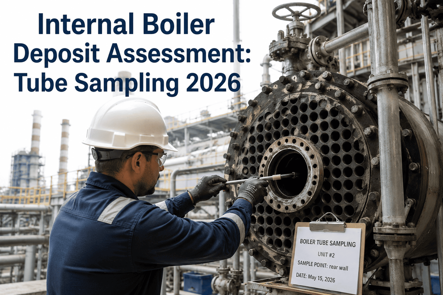
Collect Deposit Samples
Remove and label waterside and fireside deposits separately for subsequent chemical or XRF analysis in the laboratory
5
Extract Tube Sample
Cut a section spanning the failure and into undamaged material, preserving the as-found condition for metallurgical examination
6
Review Operating Logs
Check for temperature excursions, load swings, water level events, and startup or shutdown anomalies near the failure date
7
Audit Water Chemistry
Review pH, conductivity, dissolved oxygen, and treatment chemical dosage records for the period leading up to the failure
8
Cross-Reference History
Compare findings with previous failure records at the same location to identify whether this is a repeat pattern or a new issue
Turn Every Tube Failure Into a Corrective Action, Not Just a Repair.
iFactory captures failure morphology, thickness data, operating conditions, and lab results in a single structured record so your team identifies the mechanism correctly the first time.
Common Questions
Boiler Tube Failure Analysis — Frequently Asked
Can visual inspection alone identify the failure mechanism?
Visual inspection is the critical first step and can narrow the mechanism down to two or three candidates in most cases, but it rarely confirms a single mechanism on its own. The morphology you observe on the outside, such as a thin-edged rupture versus a thick-edged creep break, points you in the right direction. However, confirming the mechanism requires correlating what you see with wall thickness measurements, deposit analysis, microstructural examination, and operating history. Plants that rely solely on visual inspection frequently misidentify the root cause, which is why repeat failures remain so common across the industry.
Book a demo to see how iFactory structures this multi-layer analysis approach.
What is the most commonly misidentified boiler tube failure?
Long-term overheating is the most frequently misidentified mechanism because the external appearance can look similar to short-term overheating at a glance. Both produce longitudinal ruptures, but the edge thickness tells a completely different story about what happened inside the tube. Short-term overheating produces thin, knife-edge ruptures with no microstructural change, while long-term overheating produces thick-edged ruptures with spheroidized carbides visible only under a microscope. When a plant sees a longitudinal rupture and assumes short-term overheating without checking the microstructure, they miss the real problem of sustained temperature excursion over a long period.
Contact support for guidance on setting up proper failure classification at your plant.
How does water chemistry influence tube failure mechanisms?
Water chemistry is directly linked to at least three of the six primary failure mechanisms and indirectly influences others. Flow accelerated corrosion is entirely driven by water chemistry parameters including pH, dissolved oxygen, and flow velocity, and it can be virtually eliminated with proper chemistry control. Hydrogen damage occurs when acidic conditions at the tube wall generate atomic hydrogen that diffuses into the steel, causing decarburization and intergranular cracking over time. Caustic stress corrosion cracking requires concentrated sodium hydroxide at the tube surface, which happens when localized boiling concentrates treatment chemicals beyond their solubility limit in crevices or under deposits.
Book a demo to explore how iFactory tracks chemistry data against failure patterns.
When should a tube sample be sent for metallurgical analysis?
Any tube failure where the mechanism is not immediately obvious from visual inspection and operating conditions should be sent for metallurgical examination without exception. This includes failures where wall thickness is normal but the tube still ruptured, failures at welds or bends where stress corrosion is suspected, and any failure in a location that has experienced repeated damage over multiple outages. Metallurgical analysis reveals microstructural changes like carbide spheroidization, decarburization, and intergranular cracking that are completely invisible to the naked eye but definitive in identifying the true mechanism. Skipping this step to save time or money almost always costs more in the next unplanned outage when the same failure recurs.
Contact support to discuss integrating lab analysis into your failure workflow.
How can a plant reduce repeat tube failures over time?
The single most effective step is building a structured failure analysis process that captures morphology, thickness data, operating conditions, and lab results for every tube failure event in a consistent format. When each failure is documented against the same framework, patterns emerge that are completely invisible when failures are handled ad hoc with different people using different methods each time. A plant might discover that eighty percent of its superheater failures share the same root mechanism that was never identified because each event was treated as isolated. Coupling this documentation with water chemistry monitoring, inspection scheduling, and corrective action tracking closes the loop between failure observation and prevention.
Book a demo to see how iFactory builds this failure intelligence into your daily operations.
Stop Patching the Same Tube Failure Every Outage Cycle
Structured failure analysis, morphology tracking, mechanism identification, and corrective action closure, built for the way boiler tube failures actually happen on the plant floor.