High energy piping systems carry steam at pressures above 750 psi and temperatures above 800°F through plant corridors that operators walk past every shift. The pipes look unchanged from the outside for decades. Inside, creep is redistributing stress through the wall thickness, fatigue is cycling welds through tension and compression with every startup, and erosion is thinning bends that were never included in the original thickness baseline. When a high energy pipe fails, it does not leak. It releases its entire energy content in a fraction of a second, and the blast radius extends well beyond the pipe rack. An ASME B31.1-compliant HEP program exists to make sure that never happens on your watch. Book a demo to see how iFactory structures your HEP program around actual pipe condition data rather than generic code intervals.
A HEP Program Is the Only Thing Standing Between Your Plant and a Rupture Event
ASME B31.1 requires a documented high energy piping inspection program. Building one that actually prevents failures means going beyond minimum compliance to a system that tracks every weld, every bend, and every foot of pipe against real degradation data.
What Actually Qualifies as High Energy Piping
ASME B31.1 defines high energy piping by operating conditions, but the practical scope of a HEP program extends to every component whose failure would release sufficient energy to cause personnel injury or major equipment damage. The boundaries matter because omitting a qualifying line defeats the purpose of the entire program.
Pressure Above 750 psi AND Temperature Above 800°F
This is the ASME B31.1 threshold that triggers mandatory HEP program inclusion. Main steam and hot reheat lines at fossil plants almost universally exceed both limits. Any piping system operating above both thresholds must be in the program regardless of diameter, length, or perceived criticality.
Pressure Above 1025 psi OR Temperature Above 900°F
Many owner-operators extend HEP program coverage to systems that exceed either threshold independently, not just both. This captures cold reheat piping that may operate at lower temperature but high pressure, as well as auxiliary steam lines that reach high temperature at moderate pressure. Best practice is to include any line where a rupture would produce a high-energy release.
Lines Routing Through Occupied Areas or Near Critical Equipment
Even lines below the ASME numerical thresholds may warrant HEP program inclusion based on their routing. A 600 psi extraction steam line running above a control room or alongside a turbine pedestal carries consequences that exceed what the pressure-temperature numbers alone suggest. Risk-based inclusion closes the gap between code minimum and plant safety.
The Three Piping Systems and Their Distinct Failure Modes
Main steam, hot reheat, and cold reheat lines each operate in a different stress-temperature regime that produces a different dominant degradation mechanism. A HEP program that treats them identically will miss the most likely failure mode on at least two of the three.
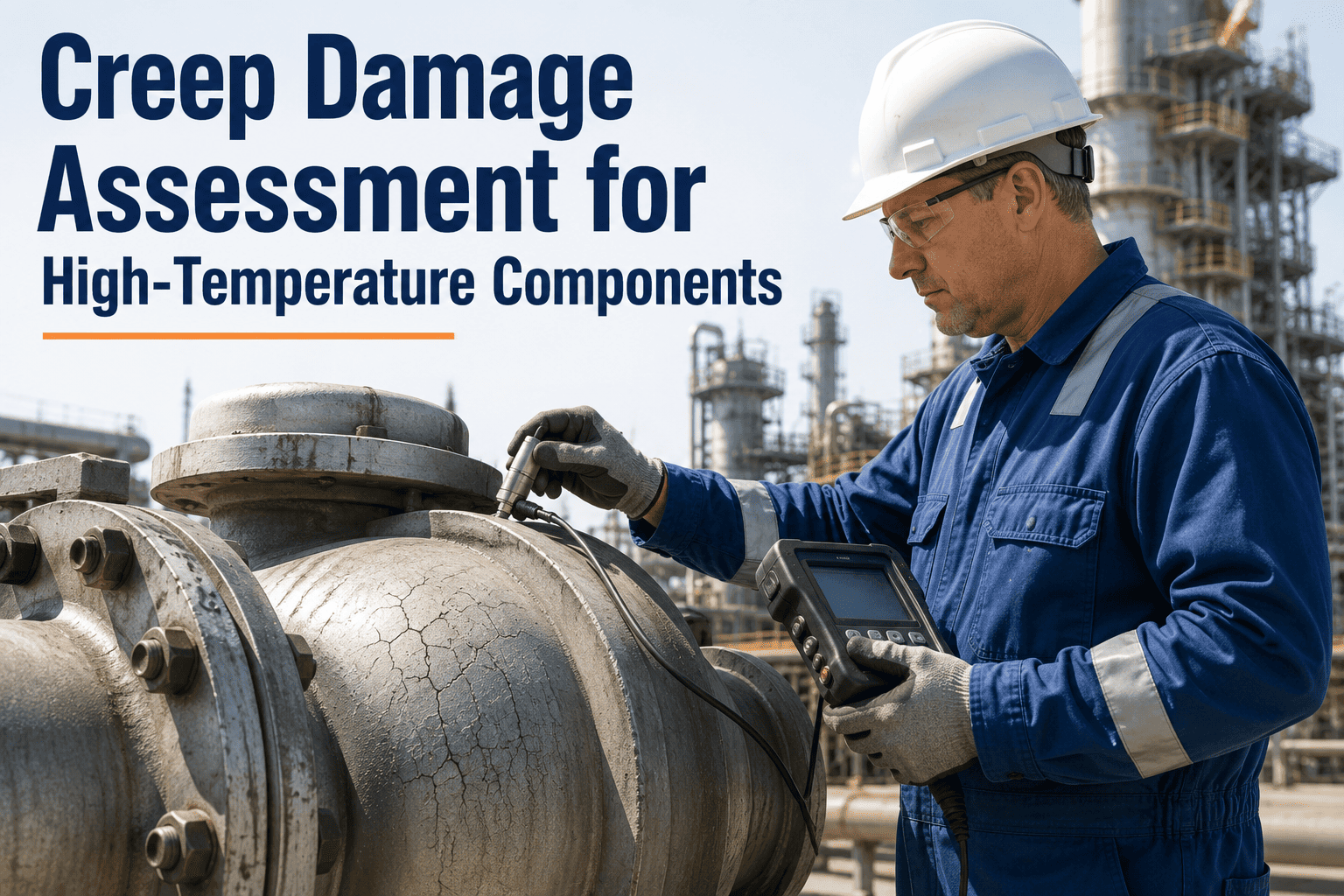
Creep is the primary concern at these temperature-stress combinations. Damage concentrates at longitudinal seam welds, elbow extrados, and branch connection welds. Creep voids nucleate at grain boundaries over 100,000+ hours of service and coalesce into cracks that propagate through the wall. Inspection must target these locations with replica metallography, UT thickness trending, and periodic weld volumetric examination.
Lower pressure but same temperature range as main steam means creep is still active, but the lower design stress combined with larger diameter and thinner walls increases susceptibility to thermal fatigue at support locations and terminal connections. The combination of creep damage and fatigue crack growth can reduce life below what either mechanism would predict independently.
Below the creep threshold for most steels, cold reheat lines degrade primarily through thermal fatigue at welds and flow-accelerated erosion at bends, especially downstream of attemperation spray nozzles where incomplete mixing creates wet steam impingement. Thickness measurements at bends and MT at welds are the primary inspection tools, with particular attention to spray nozzle downstream sections.
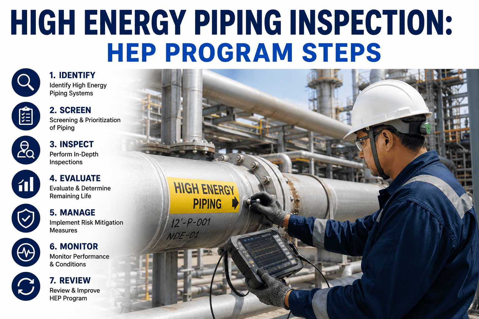
ASME B31.1 HEP Program: The Six Required Elements
A compliant HEP program is not a set of inspection activities. It is a documented management system that covers piping system identification through to ongoing condition monitoring. Missing any one element leaves a gap that an auditor or an incident investigation will identify.
Piping System Identification
Every high energy piping system must be identified, catalogued, and documented with its design conditions, material specifications, original thickness data, and support design. This is the foundation of the program. Without accurate baseline documentation, every subsequent inspection and assessment is referenced to assumptions rather than facts.
Component and Location Listing
Every weld, elbow, bend, tee, valve, and support in each piping system must be listed with a unique identifier, material specification, and design data. The inspection program examines specific components at specific locations, not vague pipe runs. Without this granularity, inspection coverage cannot be verified and findings cannot be trended over time.
Design Data Compilation
Original design calculations, stress analysis reports, and fabrication records must be assembled and reviewed. This includes design pressure, temperature, allowable stress, corrosion allowance, and the original thickness baseline used to calculate minimum required thickness. Discrepancies between design documents and as-built conditions must be resolved before inspection data can be evaluated against acceptance criteria.
Inspection Plan Development
A documented inspection plan specifies which components are examined, which NDE techniques are applied, what acceptance criteria are used, and what the inspection interval is for each system and component type. The plan must be risk-informed, meaning that higher-risk locations receive more frequent and more thorough examination than lower-risk locations within the same piping system.
Inspection Execution and Documentation
Inspections are performed per the plan by qualified NDE personnel using procedures that meet applicable code requirements. Every finding is documented with location, technique, indication size, and disposition. Results are compared against previous inspection data at the same locations to determine whether degradation is progressing and at what rate.
Condition Assessment and Life Evaluation
Inspection findings are evaluated against the original design data and applicable code rules to determine whether each component can continue in service, requires repair, or must be replaced. For components subject to creep, a remaining life estimate is calculated using operating history, material condition data, and analytical methods such as Larson Miller parameter analysis or API 579 fitness-for-service assessment.
See Your HEP Program Visualized by System and Component
iFactory maps every weld, bend, and support in your high energy piping systems against inspection findings, operating hours, and degradation trends so you can see exactly where your program has gaps.
Inspection Interval Matrix by System and Component Type
ASME B31.1 does not prescribe a single inspection interval for all high energy piping. The interval depends on the piping system, the component type, the dominant degradation mechanism, and the findings from previous inspections. This matrix represents industry-standard practice for fossil-fired power plants.
What HEP Inspections Actually Find: Top Defect Categories
Across hundreds of HEP inspection campaigns in fossil-fired power plants, certain defect types appear repeatedly. Knowing what to expect does not reduce the diligence required, but it does focus the inspection plan on the locations where findings are most probable.
What Breaks Down When HEP Programs Are Inadequate
Most high energy piping failures do not happen because the code is wrong. They happen because the program that was supposed to implement the code was incomplete, inconsistent, or not executed as written. These are the five failure modes of HEP programs themselves.
Incomplete System Identification
A reheat loop that is split between two contractors during construction ends up with one half in the HEP program and the other half omitted. The missing section fails 20 years later because nobody checked it. This is not a code failure. It is a program scope failure.
No Original Thickness Baseline
Thickness measurements are taken at every outage but cannot be trended because the as-built thickness was never recorded or has been lost. Without a baseline, the corrosion or erosion rate is unknown, and remaining life calculations become guesses dressed in engineering notation.
Inspection Plan Not Followed
The written plan calls for TOFD examination of 12 seam welds in the main steam system, but the outage schedule only allows time for four. The remaining eight welds are deferred with the assumption they will be caught next time. One of them contains a lack-of-fusion defect that propagates to critical length before the next outage.
Findings Not Trended Across Outages
Each outage produces an inspection report that is filed without comparison to previous reports. A 2mm creep indication found in 2018 is re-found at 6mm in 2024, but nobody connects the two reports to calculate a growth rate that would have triggered an interval reduction after the 2018 finding.
Support System Ignored
The HEP program covers the pipe but not the hangers, guides, and constant supports that control the piping stresses. When supports degrade, spring constants drift, and guide clearances close, the actual stress in the pipe diverges from the original design analysis. Fatigue cracks appear at locations the inspection plan never targeted because the stress model was no longer valid.
Frequently Asked Questions
Does ASME B31.1 mandate a specific inspection interval for all high energy piping?
No. ASME B31.1 requires that a HEP program be established and that inspections be performed at intervals determined by the owner-user based on operating experience, piping system condition, and the results of previous inspections. The code sets the framework for the program but does not prescribe a universal interval. Industry practice typically bases initial intervals on operating hours, then adjusts them based on findings. If no damage is found, the interval may be maintained or extended cautiously. If damage is detected, the interval is shortened to track progression. Book a demo to see how iFactory automates interval adjustment based on your inspection findings.
What is the difference between a HEP program and a standard piping inspection program?
A standard piping inspection program under API 570 or a general plant inspection program covers all process piping based on risk ranking and may use simplified thickness-based criteria. A HEP program specifically addresses the high-consequence failure modes associated with high energy piping, including creep, thermal fatigue, and the unique stress analysis requirements of thin-walled high-temperature systems. The HEP program requires detailed component-level documentation, specific NDE techniques for creep and fatigue detection, and remaining life estimation that goes beyond simple corrosion allowance calculations. It is a more rigorous, more detailed program for a more consequential class of equipment.
Do hangers and supports need to be included in the HEP inspection program?
Yes. ASME B31.1 and industry guidance documents such as EPRI NP-6600 explicitly include piping supports in the scope of HEP programs. Support degradation changes the stress distribution in the piping system, potentially increasing stresses at locations that were designed to lower levels. Constant load supports can lose calibration, spring hangers can bottom out or go slack, and guide and stop assemblies can seize or corrode closed. All of these conditions alter the piping analysis assumptions and must be inspected, documented, and corrected to maintain the validity of the original design basis. Talk to a specialist about integrating support inspections into your HEP program.
How does a HEP program handle piping systems with unknown or missing fabrication records?
Missing fabrication records are a common challenge in older plants. When original mill test reports, weld procedures, or as-built thickness data are unavailable, the HEP program must reconstruct the baseline through a combination of material verification testing, in-situ thickness measurement, and design re-analysis using conservative assumptions about material properties. Material verification identifies the actual material grade, which may differ from what was specified. Thickness surveys establish the current minimum thickness as a new baseline. The design analysis is then re-run with the verified material properties and measured dimensions to confirm that the piping satisfies the code at current operating conditions. This reconstruction effort is typically performed as a dedicated scope before the first full inspection cycle begins.
Can a HEP program be implemented without extending the next planned outage?
The documentation and planning elements of a HEP program, including system identification, component listing, and inspection plan development, are performed during normal operation and do not require outage access. The first inspection cycle is then phased into the scheduled outage window, prioritizing the highest-risk systems and components. For large piping systems, it is common practice to spread the initial baseline inspection across two or three outage cycles rather than attempting to examine every component in a single outage. This phased approach allows the program to begin generating data and informing interval decisions without creating an unsustainable inspection workload in any single outage. Book a demo to see how iFactory plans phased HEP implementation around your outage schedule.
Map Every Weld and Bend in Your High Energy Piping Systems
Book a 30-minute scoping call and bring your piping system list. iFactory structures your HEP program by system and component, tracks inspection findings across outages, and flags the locations trending toward your acceptance criteria.