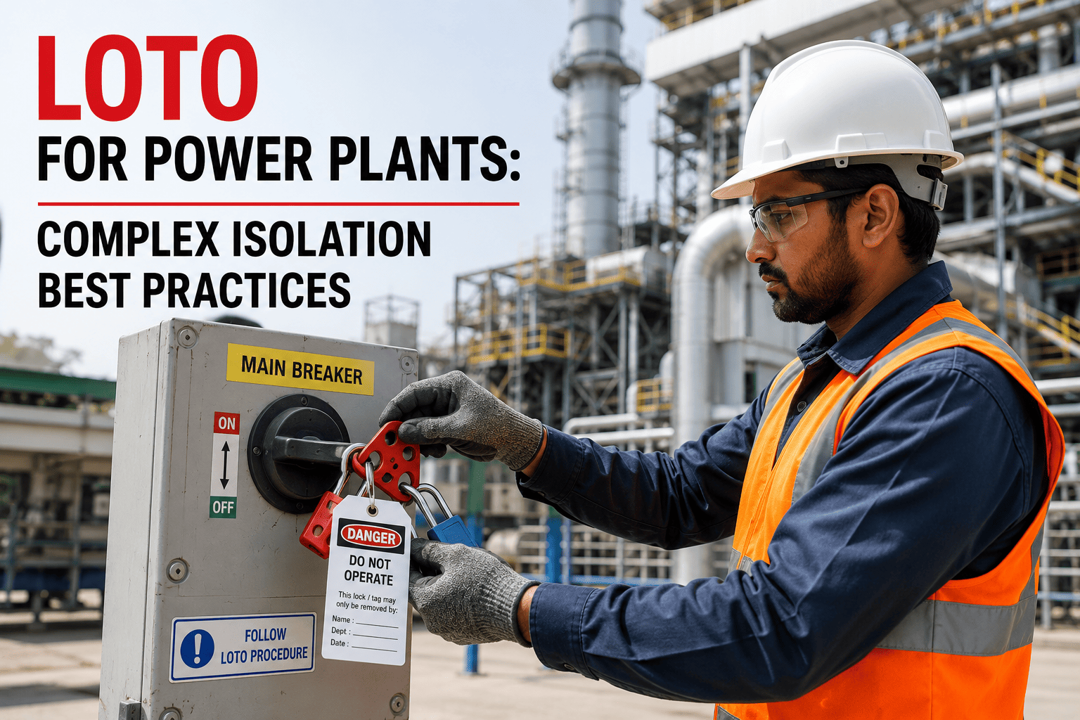
Power plant lockout/tagout is fundamentally different from the simple machine lockout that most LOTO training programs are built around. A single turbine overhaul can require isolating steam at multiple pressure levels, draining and locking hydraulic systems, de-energizing multiple voltage classes from 480V through 230kV, isolating compressed air, blocking fuel gas lines, and verifying zero-energy state at dozens of isolation points that cross mechanical, electrical, and piping discipline boundaries. OSHA 1910.147 covers the principles, but it does not provide a playbook for managing this level of multi-energy-source complexity, which is why plants that treat power plant LOTO like factory-floor LOTO end up with procedures that look compliant on paper but break down during actual execution. iFactory builds isolation management around the actual complexity of your plant systems rather than forcing your operations into a one-size-fits-all lockout template.
Standard LOTO procedures were not written for power plants
iFactory manages multi-energy-source isolation, group lockout coordination, and zero-energy verification for the kind of complex work that makes power plant LOTO a different discipline entirely.
Multi-energy-source isolation is the rule, not the exception
Factory-floor LOTO typically involves isolating one or two energy sources, applying a lock, verifying zero energy, and starting work. Power plant isolation routinely involves five to twelve distinct energy types on a single piece of equipment, each with its own isolation device, verification method, and stored energy hazard that the procedure must address. The difference is not just volume but interdependency: isolating the steam supply to a turbine also affects the boiler blowdown system, the feedwater heaters, and the steam tracing on downstream piping, which means a procedure that isolates one system without accounting for its effects on connected systems creates hazards in places the procedure never considered.
Steam and thermal energy
Multiple pressure levels from low-pressure extraction steam through high-pressure main steam, each requiring separate isolation valves, drain verification, and temperature confirmation. Stored thermal energy in steam chests, reheater loops, and insulated piping sections that remain hazardous long after the source valve is closed. Thermal expansion during isolation can shift valve positions or stress temporary blank flanges if the procedure does not account for temperature equalization timing.
Electrical energy at multiple voltage classes
A single generating unit may require LOTO on 230kV switchyard breakers, 13.8kV generator breakers, 4.16kV auxiliary power breakers, 480V motor control centers, and 120V control circuits, each with different isolation devices, different verification procedures, and different qualified person requirements. Capacitive stored energy in PT secondary circuits, surge arrestors, and DC bus capacitors requires specific discharge procedures that are easy to overlook when the focus is on the main power circuits.
Hydraulic fluid under pressure
Governor hydraulic systems, electro-hydraulic control systems, and hydraulic turbine actuator systems operate at pressures from 1,000 to 6,000 psi. Isolation requires locking pressure supply valves, verifying zero pressure at the work point, and addressing stored energy in hydraulic accumulators that can maintain system pressure even after the supply is isolated. Accumulator dump valves must be operated and verified, which is a step that simple valve-lockout procedures often omit.
Fuel gas and fuel oil systems
Natural gas supply isolation requires double block and bleed valve arrangements, gas detection verification, and purging of isolated piping sections. Fuel oil systems require isolation of both supply and return lines, heating tracing de-energization, and verification that no fuel remains in burner tip piping. The flammability of these energy sources means that verification of zero energy is not a pressure reading but a gas-free confirmation that requires atmospheric testing equipment and hold timers.
Compressed air and instrument air
Instrument air supplies to control valves and pneumatic actuators can cause unexpected valve movement if not isolated and drained. Air-operated dampers, sootblower systems, and pneumatic conveying systems all store energy in receiver tanks and pressurized piping that must be depressurized and verified. The interdependency between instrument air isolation and control system operation means that isolating air can affect systems that operators rely on for normal monitoring during the lockout condition.
Chemical energy and water treatment systems
Chemical feed systems for boiler water treatment, cooling water chemistry, and flue gas desulfurization involve corrosive and toxic chemicals under pressure or at elevated temperature. Isolation must address both the chemical hazard and any pressure or thermal energy in the system. Chemical line drains and flush procedures add steps that are unique to power plant isolation and have no equivalent in standard LOTO training materials.
Not all isolation tasks require the same procedure depth
One of the most common mistakes in power plant LOTO programs is applying the same procedure complexity to every isolation regardless of the actual energy hazard involved. Changing a filter on a cooling water pump does not require the same procedure depth as opening the turbine casing for a major overhaul, yet many plants use a single procedure template that tries to cover both situations and ends up being too detailed for simple tasks while not detailed enough for complex ones. A structured complexity classification lets your team apply the right level of procedure rigor to each isolation based on what the task actually requires.
Single-energy, single-point isolation
One energy type, one isolation device, one authorized employee. Examples include locking out a single 480V motor for bearing replacement or isolating a single low-pressure air supply for valve maintenance. Verification is straightforward and the procedure can be completed by a single qualified person without group lockout coordination.
Single-energy, multi-point isolation
One energy type but multiple isolation points required. Examples include locking out all electrical feeds to a motor control center or isolating multiple steam supply valves to a single heat exchanger. The procedure must account for all isolation points and verify zero energy at each, but energy type consistency simplifies verification methods.
Multi-energy, limited-scope isolation
Two to three energy types on a single piece of equipment. Examples include isolating a feedwater pump that requires both electrical lockout and steam seal isolation, or a forced draft fan requiring electrical isolation and bearing cooling water isolation. Interdependency between energy types begins to matter and the procedure must specify the correct isolation sequence.
Multi-energy, system-level isolation
Four or more energy types affecting multiple connected systems. Examples include a boiler inspection requiring steam, fuel gas, electrical, instrument air, and chemical feed isolation, with effects on the feedwater system, flue gas path, and sootblower systems. Group lockout is required, and the procedure must include system boundary definitions that prevent collateral isolation of systems not directly involved in the work.
Multi-energy, unit-level outage isolation
Full unit outage involving all energy types across the entire generating unit, including switchyard isolation, generator offline procedures, boiler cool-down and isolation, turbine drain and lockout, and all auxiliary system isolations. This level requires a pre-outage isolation plan, multiple group lockout coordinators, shift-transition procedures that maintain lockout integrity across crew changes, and a formal isolation status board that tracks the state of every isolation point throughout the outage duration.
Each energy type demands a different verification method
The verification step is where most power plant LOTO procedures fail, because verifying zero energy means something completely different for each energy type. You cannot verify zero electrical energy with a pressure gauge, and you cannot verify zero steam energy with a voltage tester. The table below maps the correct verification method for each energy type commonly encountered in power plant isolation, along with the stored energy hazard that the verification step must specifically address.
| Energy Type | Isolation Method | Verification Method | Stored Energy Hazard | Common Verification Error |
|---|---|---|---|---|
| Main steam | Lock closed MV and bypass valves, install blank flange | Verify zero pressure on drain valves, confirm temperature decay | Trapped steam in pockets, thermal expansion pressure | Checking valve position indicator instead of verifying zero pressure downstream |
| Electrical 4kV+ | Open and rack out breaker, apply lock and tag | Test for absence of voltage with calibrated meter at load side | Capacitive charge in cables and PT circuits | Testing at the breaker instead of at the actual work location |
| Electrical 480V | Open disconnect or breaker, apply lock and tag | Test for absence of voltage at motor terminals or load connection | VFD DC bus capacitance, backfeed from auxiliary contacts | Assuming racking out the breaker is sufficient without voltage testing |
| Hydraulic fluid | Lock supply and return valves, dump accumulator | Verify zero pressure at work point using calibrated gauge | Accumulator stored energy, pressurized lines between valves | Forgetting to dump accumulator or checking pressure at supply only |
| Natural gas | Double block and bleed, lock both block valves | Verify zero pressure and gas-free with atmospheric monitor | Gas trapped between valves, dissolved gas in liquid lines | Relying on valve position without gas-free verification with hold time |
| Instrument air | Lock supply valve, drain downstream piping | Verify zero pressure at downstream work point | Receiver tank pressure, air in long pipe runs | Isolating at the receiver only without verifying pressure at the device |
| Compressed air | Lock supply valve, open drain to atmosphere | Verify zero pressure and confirm no flow at drain | Stored air in receiver tanks and distribution piping | Not draining downstream piping after locking the supply valve |
| Chemical feed | Lock supply and isolation valves, cap open ends | Verify zero pressure, flush lines if required | Chemical residue under pressure, chemical reaction hazards | Isolating without flushing or capping, leaving chemical in the line |
Multiple crews, multiple locks, one isolation: how it actually works
Group lockout is where power plant LOTO diverges most sharply from standard practice. During an outage, a single isolation point like the main steam stop valve might need to support locks from the turbine crew, the boiler crew, the valve repair contractor, and the NDE inspection team simultaneously. OSHA 1910.147 allows group lockout under a primary authorized employee who maintains a written list of all group members, but the logistics of managing that list across shift changes, crew rotations, and partial release scenarios creates coordination complexity that paper-based systems simply cannot handle reliably. The sequence below shows how group lockout should flow in a power plant environment, and where the process breaks down without structured management.
Identify all affected employees and work scopes
Before any lock is applied, the group lockout coordinator must identify every crew, contractor, and individual who will perform work under the isolation. This includes not just the crews working directly on the isolated equipment but any crew whose work could be affected by the isolation, such as operators monitoring adjacent systems that have been impacted by the boundary decisions. Missing a single work group at this stage creates an unprotected worker.
Establish the isolation boundary and document every point
The coordinator defines exactly which valves, breakers, and devices will be isolated, using system diagrams and piping and instrumentation drawings to confirm that the boundary is complete. Each isolation point is assigned a unique identifier, its current position is verified, and the specific lockout device to be used is recorded. Boundary decisions at this stage determine whether the isolation protects everyone or leaves gaps.
Primary authorized employee applies the group lock
The primary authorized employee physically applies locks, tags, and any blank flanges or blind plates at each isolation point. This person retains primary responsibility for the isolation integrity and must verify zero energy at each point before declaring the isolation complete. The primary lock at each point secures the isolation for the entire group.
Each group member applies personal lock to group lockout device
Each authorized employee or contractor applies their own personal lock to a group lockout hasp, lock bar, or lockbox that is secured by the primary lock. This ensures that no single individual can remove the primary lock until every personal lock has been removed, which means no individual can release the isolation while anyone else is still working under it.
Verify zero energy at the work location for each crew
Each work crew independently verifies zero energy at their specific work location using the correct verification method for the energy types present. This is not a single verification by the coordinator but a per-crew verification at the point where work will actually occur. A crew working on the turbine bearings verifies zero hydraulic pressure at the bearing, not zero steam pressure at the stop valve.
Manage shift changes and partial releases through the written list
As shifts change and individual crews complete their work, the written list of group members must be updated in real time. A crew completing their portion of the work removes their personal lock, the list is updated, and the remaining crews continue under the same primary isolation. If the last crew removes their lock and the primary authorized employee removes the primary lock, the isolation is released. If any name remains on the list, the isolation must remain in place.
Paper-based group lockout lists are a single shift change away from a serious incident
iFactory tracks every lock, every group member, and every shift transition in real time so your isolation status is always accurate, not just accurate when the last person updated the paper form.
Gap between written procedure and field execution
Every power plant has written LOTO procedures that satisfy the OSHA 1910.147 documentation requirement. The problem is that written procedures describe what should happen under ideal conditions with unlimited time, qualified personnel at every step, and no pressure to complete the work quickly. Field execution happens under time pressure, with varying levels of qualification, incomplete information about system status, and the human tendency to take shortcuts when the procedure seems excessive for the perceived risk. Understanding where the gap between procedure and execution is widest helps you focus your management attention where it actually reduces incident risk rather than where it just adds paperwork.
Procedure does not match current plant configuration
After years of modifications, the written procedure references valves that have been removed, breakers that have been renumbered, and piping that has been rerouted. Operators work around these discrepancies by using what they know is correct rather than what the procedure says, which means the procedure provides no actual guidance and serves only as a compliance artifact.
Verification step treated as formality
Authorized employees check the box for zero-energy verification without actually performing the test, or they verify at a convenient location rather than at the actual work point. This is especially common when the work location is difficult to access and the verification equipment is not readily available at that location.
Stored energy hazards not addressed in procedure
Hydraulic accumulators, capacitor banks, steam pockets, and pressurized piping sections between closed valves are not identified in the procedure as stored energy hazards that require specific attention. The procedure lists the isolation points but does not specify the additional steps needed to eliminate stored energy after the primary isolation is complete.
Group lockout list not maintained during shift change
The written list of group members is accurate at the start of the shift but is not updated when a crew completes their work early or a new crew is added for an additional work scope. By mid-outage, the list no longer reflects who is actually working under the isolation, which means the primary authorized employee does not know whether it is safe to release the isolation.
Operators bypass procedure and use personal knowledge
When the procedure does not match the plant, experienced operators stop reading it and lock out based on what they know. This works when the experienced operator is the one performing the lockout, but it fails catastrophically when a less experienced operator or a contractor follows the same outdated procedure literally and isolates the wrong points.
Workers exposed to energized conditions without knowing
Skipped or falsified verification means workers begin tasks believing the energy is isolated when it is not. In hydraulic systems, this can mean opening a pressurized line. In electrical systems, it can mean contacting an energized conductor. The consequence severity is directly proportional to the energy type and level involved.
Sudden energy release during maintenance activity
Unaddressed stored energy releases unexpectedly when workers open a connection, remove a component, or break a joint that was under pressure or contained charged capacitors. The release is often violent because the workers did not expect energy to be present, which means they did not position themselves defensively or wear appropriate protection for the hazard.
Premature isolation release with workers still in the area
An outdated group lockout list allows the primary authorized employee to believe all group members have removed their locks when one or more have not. The primary lock is removed, the isolation is released, and energy is restored to equipment where workers are still performing maintenance. This is one of the most severe LOTO failure modes because it affects all workers under the isolation simultaneously.
What the standard requires versus what power plants actually need to document
OSHA 1910.147 establishes the framework for energy control programs, but it was written with general industry in mind and does not address several realities that are specific to power plant isolation. The standard requires written procedures, employee training, periodic inspections, and documentation of energy control measures, but it does not prescribe how to manage the complexity that arises when multiple energy types, multiple crews, and extended outage durations all converge on a single isolation. Power plants that rely solely on the OSHA standard as their procedural framework end up with programs that are technically compliant but operationally inadequate.
From paper procedures to a living isolation management system
iFactory replaces the stack of paper LOTO procedures, the clipboard-based group lockout lists, and the spreadsheet-based annual audit tracking with a single system that manages the entire isolation lifecycle from procedure creation through execution, monitoring, and release. The system is built around the reality that power plant isolation is complex, dynamic, and involves multiple people making coordinated decisions under time pressure, which means the system must reduce cognitive load on the authorized employee rather than adding to it.
Procedure library linked to current plant drawings
Every isolation procedure is stored in iFactory with a direct link to the current P&ID drawings and system diagrams that define the isolation boundary. When a plant modification changes a valve number, adds a bypass, or reroutes piping, the procedure is flagged for review and the drawing link is updated simultaneously so the procedure and the plant always match.
Complexity classification drives procedure selection
When a work request is created, iFactory classifies the isolation complexity based on the equipment involved and the energy types that must be isolated. The classification determines which procedure template is used, whether group lockout is required, and what level of verification is mandatory, ensuring that simple tasks do not get over-procedured and complex tasks do not get under-procedured.
Isolation point verification with energy-type-specific checks
At each isolation point, iFactory presents the authorized employee with the correct verification method for the specific energy type at that point. A steam valve shows pressure and temperature verification requirements. An electrical breaker shows voltage testing requirements. A hydraulic accumulator shows dump-and-verify requirements. The system does not allow the user to proceed until the verification is documented.
Group lockout with real-time member tracking
The group lockout coordinator maintains the member list in iFactory, and every lock application and removal is recorded in real time against a specific individual. When a shift change occurs, the outgoing coordinator hands off the active isolation to the incoming coordinator through a digital handoff that preserves the complete member list and lock status. No paper list to lose, no transcription errors, no uncertainty about who is currently under the isolation.
Partial release management for multi-crew outages
As individual crews complete their work, iFactory manages the partial release process by recording which crew members have removed their locks, updating the active member list, and confirming that the remaining isolation is still complete for the crews still working. The system prevents premature full release by requiring zero active members before the primary lock can be removed.
Audit trail for every isolation event
Every isolation event, from the initial work request through procedure selection, lock application, verification, group member changes, partial releases, and final release, is recorded with timestamps, individual identities, and the specific actions taken. This audit trail serves both as the OSHA-required periodic inspection documentation and as the investigation record if an incident occurs.
What the isolation management module does for your plant
Version-controlled procedure library
Every isolation procedure stored with revision history, approval workflow, and automatic review triggers when plant modifications affect the isolation boundary. No more procedures that reference equipment that no longer exists in its original configuration.
Energy-type-specific verification workflows
Verification steps tailored to steam, electrical, hydraulic, pneumatic, fuel, and chemical energy types so authorized employees see the correct check for each isolation point rather than a generic checklist that does not match the hazard.
Real-time group lockout tracking
Live member list, lock status by individual, shift-change digital handoff, and partial release management that prevents premature isolation release during multi-crew outage work.
Isolation boundary visualization
System diagrams and P&ID drawings with isolation points highlighted, showing exactly which valves, breakers, and devices are included in the current isolation and which adjacent systems are affected.
Competency tracking by energy type
Individual qualification records showing which energy types each authorized employee is qualified to isolate and verify, with expiration tracking and automatic alerts when qualifications need renewal.
Continuous compliance monitoring
Automated tracking of periodic inspection requirements, procedure review cycles, and training currency, with dashboard visibility into compliance status across all isolation procedures and all plant areas.
What plants achieve after implementing structured isolation management
What an isolation management pilot includes
Existing procedure audit and gap analysis
Review of your current written LOTO procedures against actual plant configuration to identify mismatches, missing stored energy hazards, and verification method gaps that need to be corrected before system deployment.
Energy source inventory by equipment
Catalog of every energy type present at each major equipment piece in your plant, forming the foundation for complexity classification and procedure selection logic in iFactory.
Isolation point database creation
Every isolation point in your plant documented with its unique identifier, energy type, associated equipment, verification method, and link to the current P&ID drawing that shows its location.
8 to 12 week pilot on selected system
Deployment on one high-complexity system such as the turbine or boiler island, covering procedure loading, group lockout workflow configuration, and live isolation execution during an actual maintenance window.
On-premise deployment
Runs on plant-network hardware so isolation data, group lockout records, and personnel qualification information remain inside your network perimeter at all times.
Managed service with 24x7 monitoring
iFactory operations team monitors system performance, data quality, and procedure currency so your safety team focuses on safe isolation execution rather than software administration.
Power plant LOTO and isolation management, explained plainly
Your isolation procedures were written for a plant that no longer exists
iFactory brings your LOTO program up to the actual complexity of your plant, with real-time group lockout tracking, energy-type-specific verification, and procedures that stay current with every modification. Book a demo.