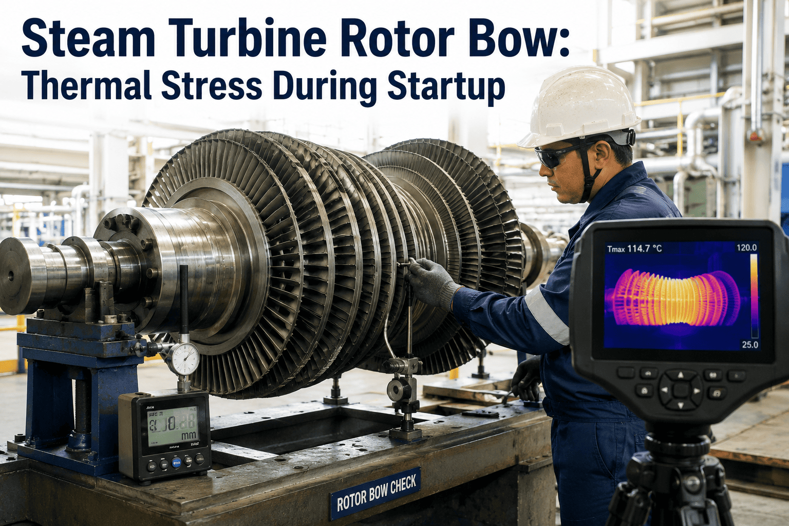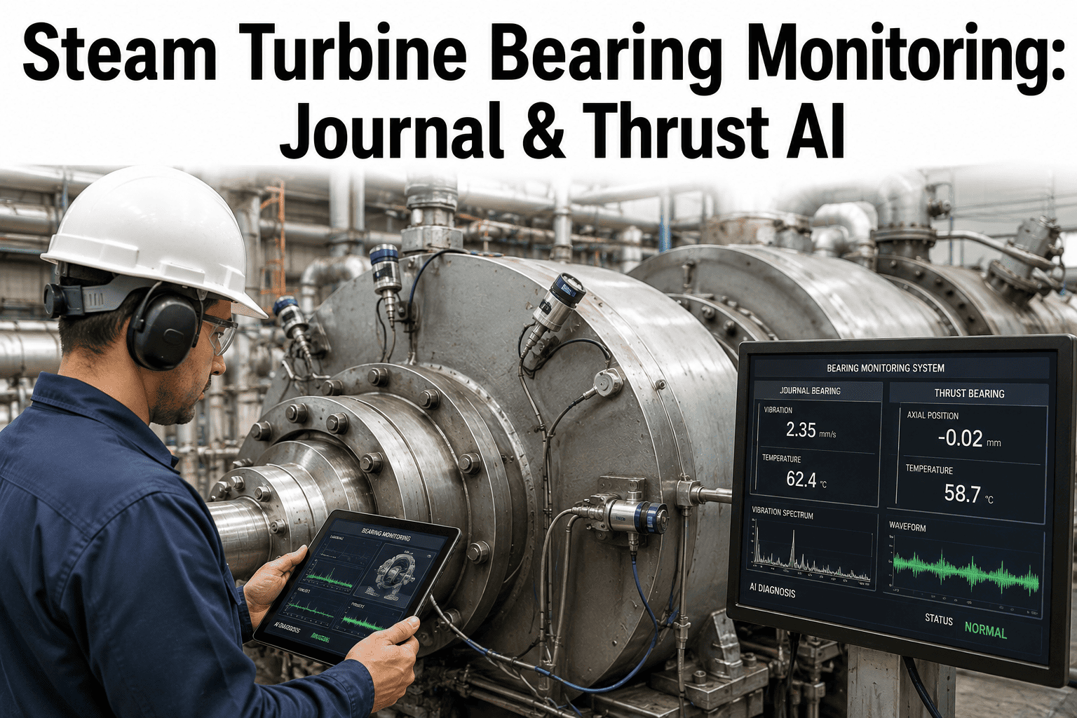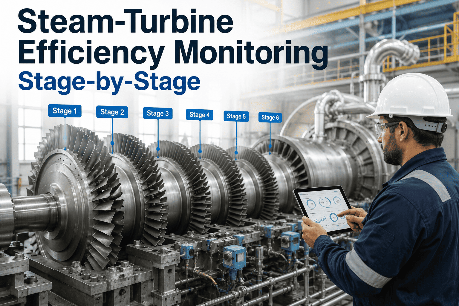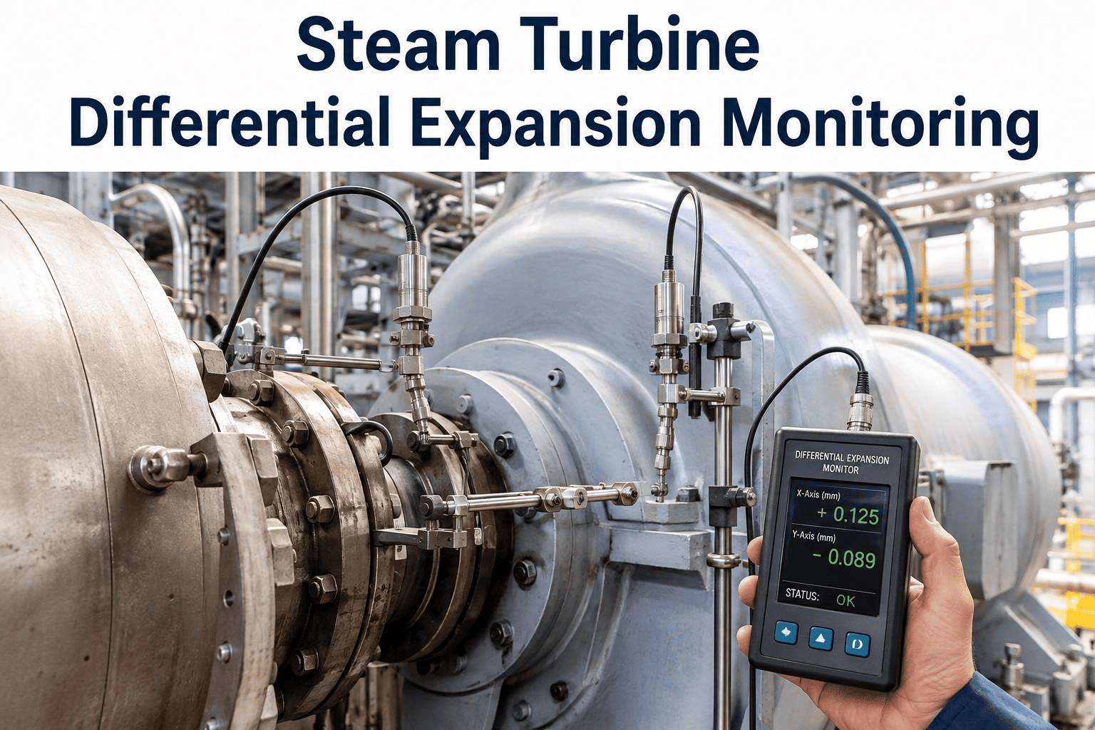
Differential expansion in a steam turbine is the difference in axial thermal growth between the rotating rotor and the stationary casing, and it is the single most critical clearance-related measurement a turbine engineer monitors during startup, shutdown, and load changes. The rotor, being a solid mass of steel with steam flowing directly over its surface, heats up and expands much faster than the thick-walled casing that surrounds it. If this difference in growth exceeds the physical axial clearance designed between the rotating blades and the stationary nozzle diaphragms, metal-to-metal contact occurs, resulting in severe rubbing that can destroy blade tips, damage seals, and force an emergency outage. AI-driven differential expansion monitoring tracks not just the absolute value but the rate of change, predicting a limit violation minutes before it happens so the operator can adjust the warming rate and prevent the rub entirely. You can book a demo to see how predictive expansion tracking protects your turbine rotors.
Steam Turbine Differential Expansion Monitoring — Predicting Axial Clearance Violations Before Rubbing Occurs
AI-powered monitoring tracks the real-time gap between rotor and casing growth, calculating the rate of differential expansion and predicting limit violations during thermal transients before traditional alarms sound.
Why the Rotor and Casing Grow at Different Rates — The Mechanics of Differential Expansion
Understanding why differential expansion occurs requires looking at the physical differences between the turbine rotor and the turbine casing, and how they interact with the steam that flows through the unit. The rotor is a solid steel forging. When steam at high temperature flows over the rotor blades, heat transfers directly from the steam to the surface of the rotor and conducts inward through solid metal. Because steel has relatively high thermal conductivity, the temperature throughout the rotor cross-section rises fairly uniformly, and the entire rotor mass begins to expand axially almost immediately after steam admission begins. The casing, by contrast, is a massive hollow structure made of thick cast iron or cast steel. Steam heats the inner wall of the casing, but that heat must conduct through a thick metal wall, and the outer surface of the casing is simultaneously losing heat to the surrounding environment through insulation. The casing wall thickness creates a significant temperature gradient between the inner and outer surfaces, and the average temperature of the casing metal lags well behind the temperature of the steam and the rotor.
The result is a predictable thermal lag: during a unit startup, the rotor heats up and grows faster than the casing, producing positive differential expansion. During a shutdown or a rapid load rejection, the opposite can occur. The rotor, having less thermal mass relative to its surface area, cools faster than the casing, causing it to contract more quickly. If the casing retains its heat, the rotor can shrink back through the casing faster than the casing shrinks, resulting in negative differential expansion. Both conditions represent a threat to axial clearances, but positive differential expansion during startup is typically the more critical challenge because the clearances at the high-pressure end of the turbine are designed to be extremely tight to minimize steam leakage and maximize efficiency.
Differential Expansion Through the Four Phases of a Cold Startup
A cold startup is the most demanding event for differential expansion management because the temperature difference between the rotor and casing is at its maximum. The operator must carefully control the rate of steam admission, the speed of the roll, and the rate of loading to give the casing time to catch up to the rotor. The timeline below maps how differential expansion typically behaves through the four critical phases of a cold startup on a large fossil or combined-cycle steam turbine, and where the risk of exceeding axial clearance limits is highest.
Positive vs. Negative Differential Expansion — Which Clearance Is at Risk
Differential expansion is not a single directional threat. The physical design of the turbine determines whether positive or negative differential expansion endangers specific axial clearances. In most large steam turbines, the rotor is anchored at a single point — typically the thrust bearing near the generator end or the front standard. All axial growth from that anchor point extends toward the high-pressure inlet. When the rotor grows faster than the casing (positive differential expansion), the rotor blades at the high-pressure end move axially closer to the stationary nozzle diaphragms at that end. When the rotor shrinks faster than the casing (negative differential expansion), the rotor blades at the opposite end of the machine move closer to the stationary components there. The operator must understand which end of the turbine is at risk under each condition, because the corrective action for positive differential expansion — slowing the warming rate — is different from the corrective action for negative differential expansion, which may require adjusting sealing steam or holding load to prevent the rotor from contracting too fast.
During startup and loading, the rotor extends out from the thrust bearing faster than the casing. The axial clearance at the high-pressure end of the turbine — where clearances are typically tightest to minimize leakage — decreases. If the positive limit is exceeded, the rotating blades contact the stationary nozzle diaphragms at the HP inlet. This is the most common and most dangerous differential expansion scenario because the HP blades operate at the highest temperatures and stresses, and rubbing damage here can rapidly propagate to blade failure. The corrective action is to reduce the steam temperature, reduce the loading rate, or hold the unit at a constant load to allow the casing to catch up.
During rapid load rejections, shutdowns, or when excessive sealing steam is applied to the LP turbine, the rotor can contract faster than the casing, or the casing can remain expanded while the rotor shrinks. The axial clearance at the low-pressure or exhaust end of the turbine decreases. While LP clearances are generally larger than HP clearances, a negative differential expansion event can still cause rubbing at the LP blade rows or at the balance piston. The corrective action depends on the cause: if it is a load rejection, the operator may need to maintain minimum load or adjust the sealing steam temperature to slow the rotor contraction rate.
Stop Relying on Alarm Limits That Trigger After the Rotor Has Already Entered the Danger Zone
See how AI differential expansion monitoring predicts the trajectory of rotor-casing growth and gives operators early warning to adjust warming rates before limits are reached.
Why Traditional Differential Expansion Alarms Are Too Late to Prevent Rubbing
The conventional approach to differential expansion protection relies on a set of absolute value alarms and trip limits configured in the DCS. When the measured differential expansion exceeds the high alarm setpoint, the operator is notified. When it exceeds the trip setpoint, the turbine is tripped to protect the hardware. This architecture has a fundamental flaw: it is reactive, not predictive. By the time the differential expansion value crosses the alarm threshold, the rotor is already dangerously close to the physical clearance limit. The operator now has only a narrow margin — sometimes as little as 0.2 mm to 0.5 mm — between the alarm point and the trip point, and almost no time to take corrective action before the trip is triggered. A turbine trip during a startup or load change is itself a severe thermal transient that causes massive thermal stress on the rotor and casing, potentially shortening the life of the rotor and creating new clearance problems on the subsequent restart.
AI-driven monitoring transforms differential expansion protection from a reactive alarm system into a predictive guidance system. Instead of waiting for the absolute value to cross a threshold, the AI platform calculates the rate of change of differential expansion in real time and uses it to project where the value will be in 5, 10, and 15 minutes if the current operating conditions continue. If the projection shows that the value will cross the alarm limit in 8 minutes, the operator is notified immediately, giving them an 8-minute window to reduce the steam temperature, slow the loading rate, or adjust the speed hold point. This early warning prevents the alarm from ever being reached, prevents the trip from ever being triggered, and protects the rotor without disrupting the startup sequence.
Four Variables AI Monitoring Correlates With Differential Expansion Behavior
Differential expansion does not change in isolation. It is driven by the thermal state of the turbine, which is determined by steam conditions, speed, load, and time. An AI monitoring system that only looks at the differential expansion sensor is no better than a DCS alarm. The value of AI comes from correlating the differential expansion signal with the process variables that cause it to change, building a multi-dimensional model that can distinguish between a normal startup trend and an abnormal trend that requires intervention.
The platform tracks the difference between the main steam temperature and the rotor metal temperature, calculating the thermal shock potential of the steam. If steam temperature is rising much faster than rotor metal temperature, the platform flags a high risk of rapid differential expansion increase and recommends reducing the steam temperature ramp rate, even if the differential expansion value itself has not yet begun to rise significantly.
The first derivative of the differential expansion signal is calculated continuously and compared against allowable rates for the current phase of operation. A high rate of change during acceleration is expected and allowed within limits, but a high rate of change during a steady load hold indicates an abnormal condition — such as a valve stem breaking and admitting high-temperature steam to a cold section of the turbine — that requires immediate investigation.
Differential expansion is measured relative to the bearing pedestal, which means any thermal growth of the pedestal itself introduces measurement error. The platform tracks bearing oil temperature and pedestal temperature to estimate pedestal growth and correct the differential expansion reading, preventing false alarms or missed alarms caused by the measurement reference point shifting.
When differential expansion approaches the physical clearance limit, the first physical symptom is often a slight increase in shaft vibration as the blade tips begin to lightly touch the stationary seals. The platform correlates real-time vibration data with differential expansion data, and if a vibration increase coincides with high differential expansion, it generates a high-priority rub warning that overrides the normal differential expansion alert hierarchy.
Differential Expansion Limits Across Turbine Sections — Understanding the Margins
The allowable differential expansion range varies significantly between the high-pressure, intermediate-pressure, and low-pressure sections of a turbine. These limits are established by the OEM during the mechanical design phase and are based on the physical axial clearances between the rotating and stationary components in each section. The table below presents typical limit ranges for a large fossil-fired steam turbine, though the actual values for any specific unit must be verified against the OEM instruction manual and the unit's specific clearance measurements from the last overhaul.
| Turbine Section | Typical Positive Limit | Typical Negative Limit | Primary Risk at Limit |
|---|---|---|---|
| High-Pressure (HP) | +2.0 mm to +3.5 mm | -0.5 mm to -1.5 mm | HP blade tip rubbing against nozzle diaphragms at the inlet end |
| Intermediate-Pressure (IP) | +2.5 mm to +4.0 mm | -1.0 mm to -2.0 mm | IP blade rubbing, often at the inner end toward the HP-IP coupling |
| Low-Pressure (LP) | +3.0 mm to +6.0 mm | -1.5 mm to -3.0 mm | LP blade rubbing, often influenced by exhaust hood temperature and sealing steam |
The HP section consistently has the tightest differential expansion margins because the HP blades are shorter and the axial clearances are designed to be minimal to maintain stage efficiency at high pressure. A differential expansion deviation of just 0.5 mm in the HP section can be the difference between normal operation and a catastrophic rub. The LP section has larger absolute limits, but negative differential expansion in the LP section is heavily influenced by sealing steam temperature, which is an independent variable that the operator must manage carefully during low-load operation and startup to prevent the LP rotor from contracting excessively while the LP casing remains warm.
Questions Turbine Engineers Ask About AI Differential Expansion Monitoring
Protect Your Turbine Rotors by Predicting Differential Expansion Violations Before They Happen
Continuous AI-driven differential expansion monitoring that calculates the rate of rotor-casing growth, predicts limit violations during thermal transients, and guides operators to adjust warming rates before axial clearances are compromised.