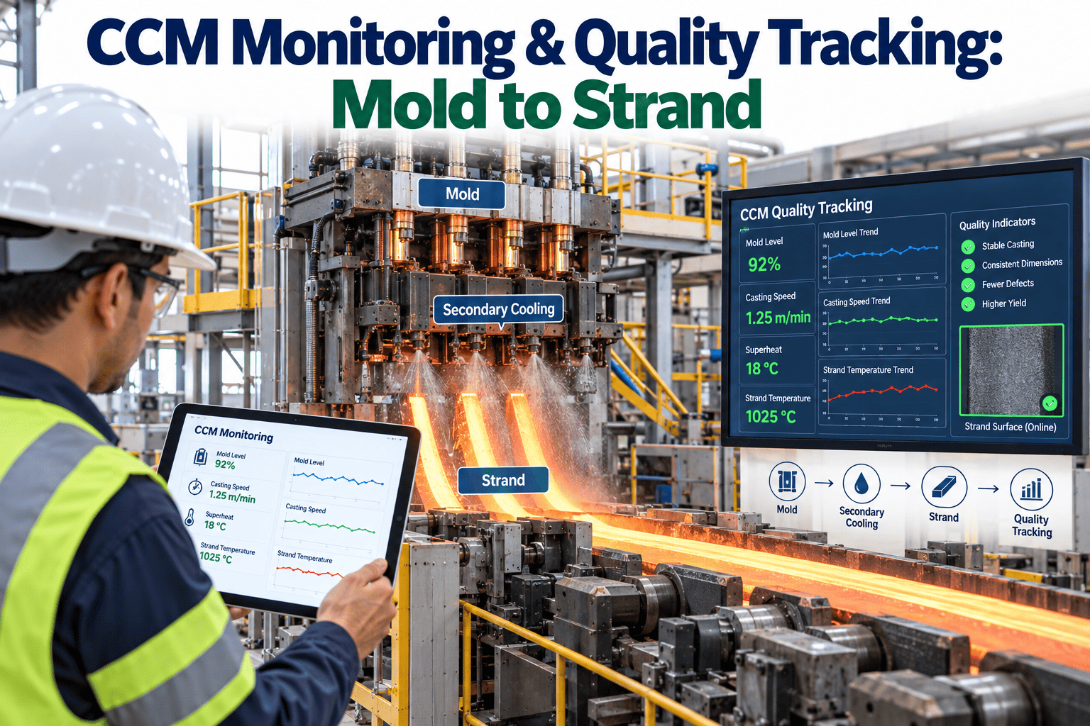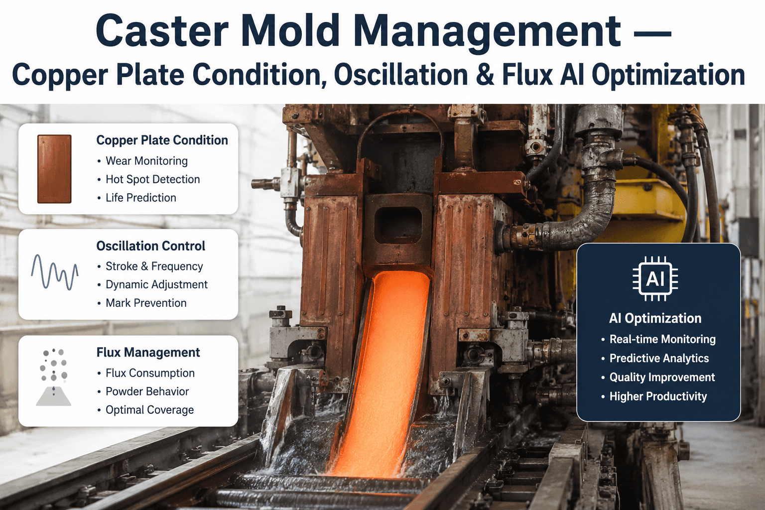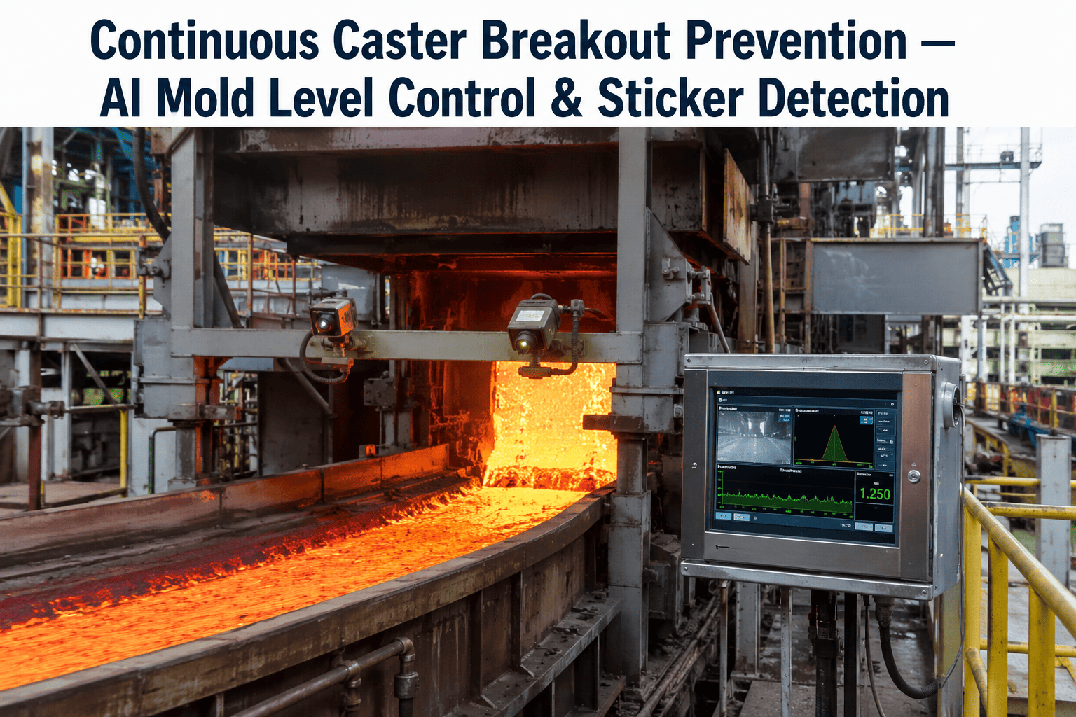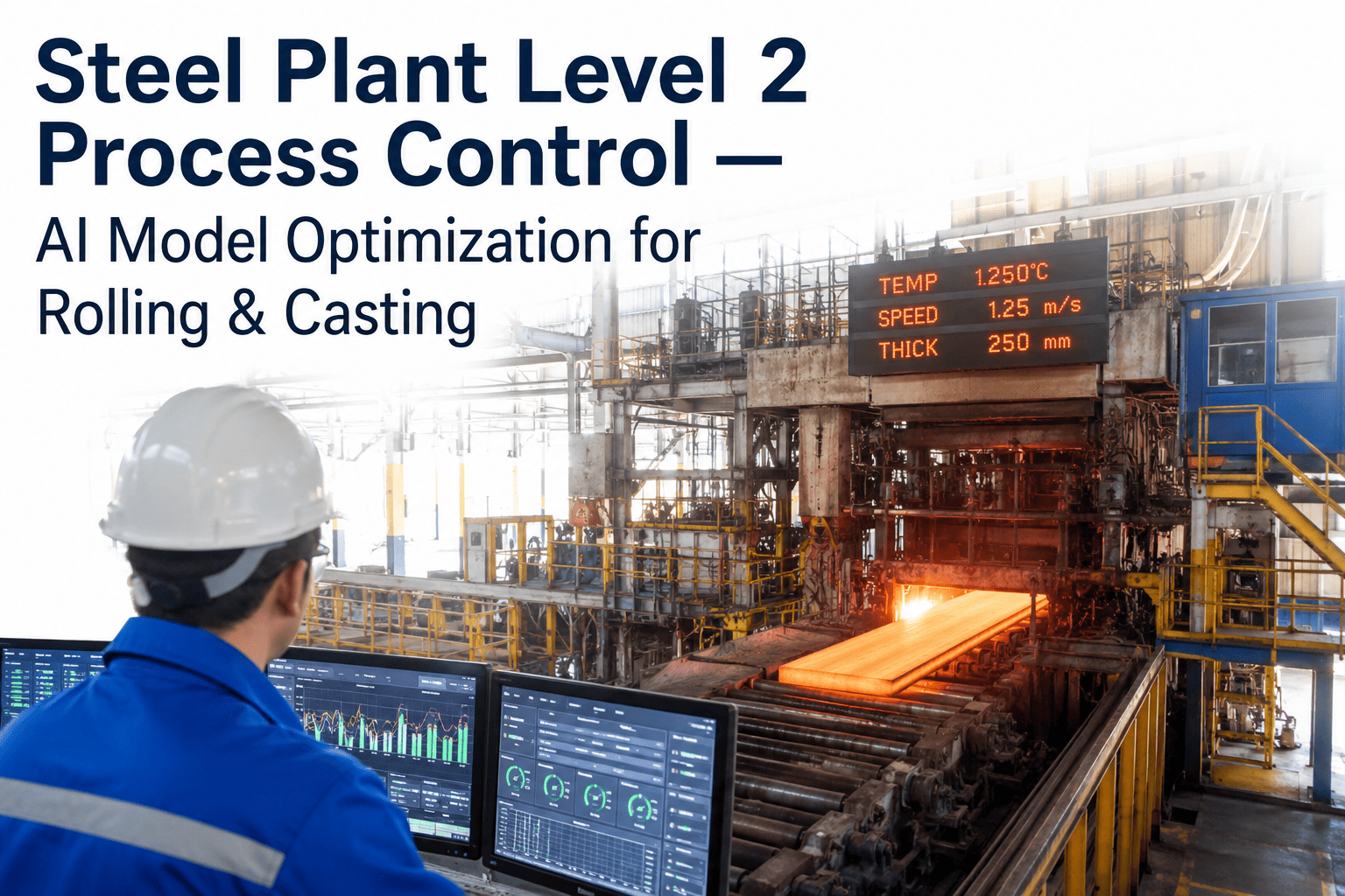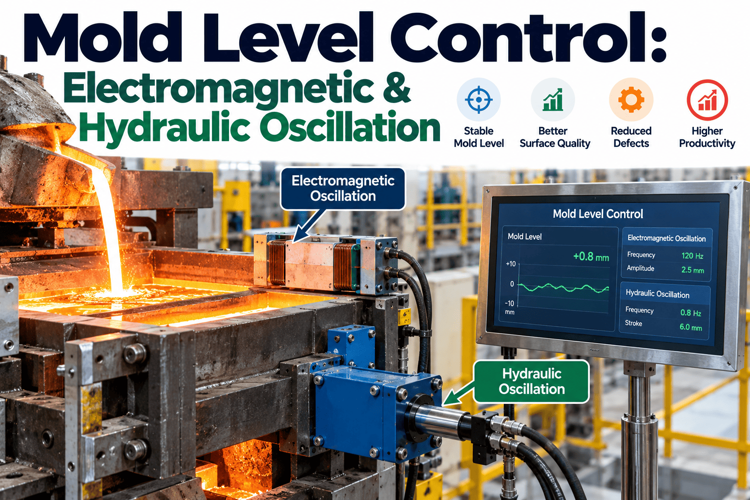
A continuous casting mold is where the entire quality outcome of a cast strand gets decided in the first few seconds of solidification, and three variables working together determine whether that outcome is clean steel or a slab full of subsurface defects. Mold level control keeps the meniscus steady so the solidifying shell forms evenly. Oscillation lubricates that shell against the mold wall so it doesn't tear. Electromagnetic stirring shapes the flow beneath the surface so inclusions and bubbles don't get trapped in it. Get any one of the three wrong and the other two can't fully compensate — the defect shows up on the rolled product weeks later, far from the caster that actually caused it. To see how real-time mold monitoring keeps all three in sync, talk to our team.
Three Systems, One Meniscus: Why Mold Level, Oscillation, and EMS Can't Be Tuned in Isolation
Mold level control, hydraulic oscillation, and electromagnetic stirring each solve a different casting problem — but they all act on the same few centimeters of molten steel, and a change to one changes the physics the other two are working with.
Mold Level Control: Why ±3mm Is the Line Between Clean Steel and a Breakout
The meniscus is where molten steel first touches the water-cooled copper mold wall and begins forming a solid shell. A stable meniscus lets that shell grow at a predictable, even rate. A meniscus that's surging up and down does something more damaging than just looking unstable on a sensor readout — it disrupts the shell exactly where it's thinnest and most vulnerable, which is the direct precursor to a breakout, one of the costliest failure modes in the entire casting process, since a breakout can mean hours of downtime, damaged equipment beneath the mold, and a safety incident depending on how much liquid steel escapes before the line is stopped.
Modern level control loops read the meniscus position continuously, typically via eddy-current or laser sensing rather than older radioactive-isotope methods, and feed that signal into a control algorithm that adjusts a stopper rod or slide gate to regulate steel flow into the mold. The tighter that loop, the more consistent the shell — but nonlinear disturbances from slag, temperature effects, and sensor interference are exactly why simple PID control alone still struggles to hold the line at high casting speeds.
Hydraulic Oscillation: The Lubrication System the Shell Depends On
The mold doesn't sit still during casting — it oscillates vertically, and that motion exists for one specific reason: to prevent the newly formed shell from sticking to the copper mold wall as it's drawn downward. Without oscillation, friction between the shell and the mold would tear the thin solid layer apart before it's strong enough to survive. Hydraulic oscillation systems have largely replaced older mechanical cam-driven designs because they allow independent control of stroke, frequency, and waveform shape — three parameters that interact in ways that aren't obvious from any one of them alone.
The parameter that actually governs most of what matters — oscillation mark depth, hook formation, and mold flux consumption — isn't stroke or frequency individually. It's negative strip time, the portion of each oscillation cycle where the mold is moving downward faster than the strand itself, which is what generates the compressive force that helps close the meniscus and control lubrication. Get the balance of stroke, frequency, and casting speed wrong, and negative strip time drifts out of its effective range even if each individual setting looks reasonable on its own.
Talk Through Your Caster's Level, Oscillation, and EMS Setup
Bring your current mold instrumentation and control setup to the call. We'll walk through how real-time monitoring flags when these three interacting systems drift out of their coordinated operating window.
Electromagnetic Stirring: Shaping the Flow Beneath the Surface
While level control and oscillation manage what happens right at the meniscus, in-mold electromagnetic stirring, or EMS, works on the bulk flow of molten steel just beneath it. An EMS coil applies a moving magnetic field to the liquid steel, inducing a swirling flow that does two things at once: it helps float non-metallic inclusions and trapped gas bubbles up and away from the solidifying shell, and it evens out the temperature distribution across the strand, which produces a more uniform microstructure at the surface and just below it. Some caster designs pair a primary stirring coil with a second coil dedicated specifically to controlling flow right at the free surface, since the requirements for bulk mixing and meniscus-region flow control aren't always the same thing.
The strength and pattern of that stirring matters as much as the fact that stirring is happening at all. Too weak, and inclusions aren't cleared effectively. Too strong, and the mush zone at the solidification front can enlarge and accelerate in ways that create their own defects. Getting the magnetic field's travel speed and flux density into the right operating window — rather than simply turning EMS on — is what separates a stirring system that improves surface quality from one that's just consuming power.
| System | Primary Function | What It Disturbs If Miscalibrated |
|---|---|---|
| Mold Level Control | Keeps meniscus position stable within a tight band | Surging level disrupts shell formation and can overwhelm EMS flow patterns |
| Hydraulic Oscillation | Lubricates shell against mold wall, controls flux consumption | Wrong negative strip time deepens oscillation marks and changes meniscus behavior |
| Electromagnetic Stirring | Clears inclusions and gas, homogenizes temperature below surface | Over-strong stirring can disturb the meniscus level control is trying to hold steady |
Mold Flux Behavior: The Interface Layer That Ties Everything Together
Mold flux sits on top of the molten steel meniscus and does several jobs simultaneously — it insulates the steel surface thermally, absorbs inclusions that float up from below, and most critically, it flows down into the gap between the shell and the mold wall to provide the lubrication that oscillation is designed to enable. Flux consumption rate is one of the more counterintuitive metrics in the whole process: it correlates more reliably with positive strip time than with the frequency setting most operators watch, and the relationship between stroke length and consumption doesn't always move in the direction intuition suggests — a shorter stroke has been observed to consume more flux under some conditions, the opposite of what a simple mental model would predict.
Because flux consumption ties directly back to oscillation parameters, and oscillation marks are where most flux gets consumed in the first place, flux behavior is really a downstream signal of how well the oscillation system is tuned — not a separate variable to manage on its own. A caster reporting inconsistent flux consumption from shift to shift is very often reporting an oscillation problem, not a flux problem.
Why Grade and Speed Transitions Are the Highest-Risk Moments
Steady-state casting at a fixed speed and steel grade is where all three systems have the most time to settle into a stable, coordinated rhythm. Transitions are where that coordination gets tested hardest. When casting speed changes, oscillation frequency has to track it closely enough to hold negative strip time ratio roughly constant, mold level control has to adapt its response to a different flow rate without overshooting, and EMS parameters that were tuned for one speed may no longer sit in the right operating window for the next.
Grade changes add a second layer of complexity on top of speed changes, since different steel chemistries solidify differently and can call for different flux products with different melting and flow characteristics. A control system that handles steady-state casting well can still struggle specifically during the transition window, which is exactly why defect rates on many casters cluster disproportionately around grade and speed changes rather than being spread evenly across the whole heat.
What Coordinated Monitoring Actually Looks At
Treating mold level, oscillation, and EMS as three separate dashboards means a plant only sees a problem after it's already shown up as a defect, because no single system's data tells the whole story on its own. A level sensor reading a small surge might look unremarkable in isolation, but the same reading alongside an oscillation cycle that's drifted out of its coordinated window and an EMS field that's running stronger than usual tells a very different story — one where three individually minor deviations are compounding into a real defect risk.
Coordinated monitoring pulls level position, oscillation stroke and frequency, negative strip time, and EMS field parameters into a single continuous view, correlated against casting speed and grade in real time. The value isn't just visibility — it's catching the moment where the three systems start drifting apart from the coordinated operating window that produces clean steel, early enough in a heat to correct it rather than discovering the defect on a rolled coil days later.
| Approach | What It Sees | What It Misses |
|---|---|---|
| Isolated Dashboards | Each system's own readings against its own setpoint | How the three systems' small deviations are compounding together |
| Coordinated Monitoring | Level, oscillation, and EMS correlated against speed and grade in real time | Little — the correlation itself is the signal that catches compounding drift |
How Defects Trace Back to Which System Failed
Frequently Asked Questions
Monitor Mold Level, Oscillation, and EMS Together, Not as Separate Dashboards
A turnkey AI deployment brings level position, oscillation parameters, and stirring behavior into one live view, so a drift in any one system is caught before it shows up as a defect on the rolled product weeks later.