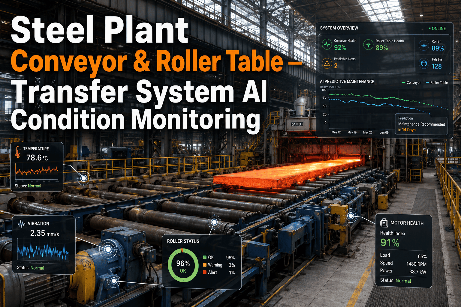
Steel Plant Conveyor & Roller Table — Transfer System AI Condition Monitoring
By James Smith on July 3, 2026
Roller tables and transfer systems are the connective tissue of any steel plant, moving slabs from the caster to the reheating furnace, transferring bars through the cooling bed, and shuttling coils through the finishing line. For reliability engineers, these systems present a unique monitoring challenge because they consist of hundreds of individual rollers distributed across long transfer lines where a single bearing failure on one roller can cascade into surface damage on every piece of material that passes over it before anyone notices the problem. Traditional periodic inspection walks catch only a fraction of developing faults, and by the time a roller is flagged as hot or noisy during a routine check, the damage to both the roller assembly and the product it has been handling is already done. AI condition monitoring changes this dynamic by tracking the health of every roller, motor, and drive on the transfer line simultaneously, catching bearing degradation, misalignment, and imbalance conditions days or weeks before they would be detected through manual methods, and reliability teams can see how this works against their own transfer system configuration.
TRANSFER SYSTEM CONDITION MONITORING
AI Condition Monitoring for Steel Plant Conveyors and Roller Tables
Track bearing degradation, motor health, and alignment across every roller on your transfer lines from continuous caster to coil staging, catching faults before they damage product.
The Transfer Line: Where One Failed Roller Damages Everything Downstream
Material in a steel plant passes through multiple transfer systems between every major process stage. Each transfer point is a reliability risk node where a single degraded roller can imprint defects onto hot steel surfaces, disrupt material tracking, or trigger unplanned line stoppages that cascade through the entire production sequence.
Caster Discharge
Slab Transfer Table
Roller mark imprinting on hot slabs
Reheat Furnace Entry
Entry Roller Table
Skid mark compounding from misaligned rollers
Mill Delivery
Approach Table and Lifting Tables
Delivery timing disruption from seized rollers
Cooling Bed
Walking Beam or Chain Transfer
Straightness deviation from uneven transfer
Coil Handling
Coil Conveyor and Turnaround
Coil edge damage from degraded chain rollers
What AI Actually Monitors on Each Roller Assembly
Every roller on a transfer table is a system with multiple failure modes, and AI condition monitoring tracks each component independently rather than treating the roller as a single point that either works or does not. This component-level tracking is what lets reliability engineers prioritize maintenance on the specific part of the roller assembly that is actually degrading rather than replacing the entire unit on a fixed schedule.
BR
Bearing Condition
Vibration signature analysis detects inner race, outer race, and ball defect frequencies specific to the bearing geometry installed in each roller position, with severity trending that predicts remaining useful life based on degradation rate.
AL
Shaft Alignment
Axial and radial vibration patterns reveal misalignment between the roller shaft and the drive coupling that accelerates bearing wear and creates periodic speed fluctuations that imprint surface patterns on hot material.
MH
Motor and Drive Health
Current signature analysis and thermal trending on individual roller motors detect stator winding degradation, rotor bar faults, and drive coupling wear before they cause the roller to stall under load during a transfer operation.
SP
Speed and Synchronization
Tachometer or encoder data across the roller table is analyzed for speed variations between adjacent rollers that indicate slipping, mechanical binding, or drive faults that disrupt material transfer timing and tracking accuracy.
TH
Thermal Profile
Temperature sensors on bearing housings track heat generation trends that indicate increasing friction from lubrication breakdown, contamination ingress, or mechanical overload, with rate-of-rise alerts that catch rapid deterioration.
LU
Lubrication Effectiveness
Ultrasonic or acoustic emission sensors monitor the lubrication film condition within bearings, detecting when grease paths are blocked, when contamination has degraded the lubricant, or when re-greasing intervals need adjustment.
Failure Modes by Transfer System Type
Transfer System
Dominant Failure Mode
Product Impact If Undetected
Detection Window with AI
Slab Transfer Table
Bearing seizure from heat soak and scale ingress
Roller marks on slab bottom surface, caster delay
14-21 days before functional failure
Reheat Furnace Entry Table
Roller speed drift from drive degradation
Slab tracking error, skid mark misalignment
7-14 days before speed exceeds tolerance
Mill Approach Table
Coupling wear causing torsional vibration
Delivery timing jitter, bar curvature on entry
10-18 days before coupling failure
Runout Table
Water-cooled roller seal failure
Roller surface damage imprinting on strip bottom
5-10 days before water ingress damages bearing
Cooling Bed Transfer
Chain roller bearing degradation
Uneven transfer causing bar straightness deviation
12-20 days before chain derailment risk
Coil Conveyor
Chain stretch and roller flat spotting
Coil edge damage, staging position errors
8-15 days before replacement required
Alert Severity Framework: From Early Warning to Critical Action
AI condition monitoring for roller tables generates a continuous stream of health data on every monitored roller, and without a clear severity framework, reliability teams get overwhelmed by alerts and start ignoring the system entirely. The tier structure below maps each alert level to a specific maintenance response and time window, ensuring that the monitoring system drives action rather than noise.
Tier 1
Watch
Vibration or thermal trending shows early deviation from baseline but remains within normal operating envelope
Log in condition monitoring system, increase inspection frequency to weekly, verify lubrication schedule compliance
Action within 30 days
Tier 2
Caution
Vibration amplitude exceeds alert threshold or temperature rate-of-rise indicates accelerating degradation
Schedule maintenance at next planned downtime, order replacement parts, plan roller change-out procedure
Action within 7-14 days
Tier 3
Critical
Vibration at or above alarm threshold, bearing defect frequencies confirmed, or temperature exceeding safe operating limit
Plan immediate replacement at next shift change or short stoppage, prepare contingency for transfer line speed reduction if delay occurs
Action within 24-48 hours
Tier 4
Emergency
Imminent failure indicated by rapid vibration escalation, thermal runaway, or confirmed mechanical damage detected in signatures
Take roller out of service immediately, implement transfer line speed restriction if needed, execute emergency change-out
Action immediately
Sensor Deployment Sequence for Roller Table Monitoring
Deploying condition monitoring across a roller table with 200 or more individual rollers requires a phased sensor installation strategy that balances coverage breadth with data quality and budget pacing. The sequence below represents the most cost-effective deployment order for a typical slab or strip transfer line.
1
Phase 1
Critical Path Rollers — Entry, Exit, and Speed-Critical Positions
Install vibration and temperature sensors on the first five and last five rollers of each transfer table section, plus any rollers that control material tracking or timing. These positions have the highest product impact if they fail and typically represent 15 to 20 percent of total roller count while covering 80 percent of the failure-to-product-damage exposure.
2
Phase 2
High-Load Zone Rollers — Under Hot Material and Heavy Sections
Extend monitoring to rollers in zones where slab or billet weight and temperature create the harshest operating conditions, including the center section of long transfer tables where material dwell time is highest. These rollers experience accelerated thermal cycling and bearing loading that makes them statistically more likely to develop faults between inspection intervals.
3
Phase 3
Full Table Coverage — Remaining Rollers and Drive Motors
Complete the monitoring installation across all remaining roller positions and add current signature monitoring on individual drive motors. Full coverage enables the AI system to detect patterns across the entire table, such as systematic alignment issues that only become visible when you can compare the health profile of every roller simultaneously rather than sampling individual positions.
Reliability Impact Metrics from AI Roller Table Monitoring
68%
Reduction in unplanned roller table stoppages after AI condition monitoring deployment on hot transfer lines
3.2x
Improvement in mean time between roller replacements when moving from time-based to condition-based change-out schedules
41%
Decrease in roller-mark-related surface defects on downstream finished product after first year of monitoring
22%
Reduction in roller table spare parts consumption when bearing replacements are triggered by condition rather than calendar schedules
Frequently Asked Questions
Sensors deployed on roller tables in high-temperature zones use industrial-grade accelerometers rated for continuous operation above 150 degrees Celsius, combined with protective mounting hardware that provides thermal isolation between the bearing housing surface and the sensor electronics. In zones where radiated heat exceeds even these ratings, remote sensor mounting with waveguides or acoustic emission sensors that can be positioned farther from the heat source are used instead. The AI models are trained to account for the temperature-dependent changes in vibration signal characteristics that naturally occur as roller bearings operate at different thermal states, so a hot roller in a normal operating range does not generate false alerts simply because its baseline vibration signature differs from a roller on a cooler section of the same table. Reliability teams evaluating sensor options for their specific temperature zones can book a demo to review hardware configurations matched to their transfer line conditions.
A standard slab transfer table with 120 to 180 rollers typically requires one triaxial vibration sensor and one temperature sensor per monitored roller position, which means a full installation ranges from 240 to 360 sensor channels for the roller bodies alone, plus additional current sensors on individual drive motors. However, the phased deployment approach means the initial installation covers only 20 to 30 percent of these positions, bringing the starting sensor count down to 50 to 100 channels that can be installed during a single planned outage. The data acquisition infrastructure is sized for full deployment from the start, so adding sensors in subsequent phases requires only mechanical installation and configuration without replacing any upstream hardware or software components. Teams planning sensor budgets can discuss configuration options with support.
Yes, the vibration signatures generated by a degrading bearing and by a damaged roller surface are mechanically distinct and produce different frequency patterns that the AI classification model can separate reliably. Bearing defects generate energy at specific defect frequencies determined by the bearing geometry, roller diameter, and rotational speed, while surface damage on the roller body itself typically produces broadband vibration changes that occur once per revolution and are modulated by the contact pattern between the roller surface and the material passing over it. In practice, these two failure modes often coexist because a bearing fault allows the roller to run eccentrically, which then accelerates surface damage, so the AI system tracks both degradation paths independently and flags when a bearing condition alert has progressed to the point where roller surface damage is likely already occurring. This dual-path tracking is what lets reliability engineers make informed decisions about whether a roller can safely run until the next planned outage or needs immediate replacement to prevent product damage.
The condition monitoring platform generates structured alert data with severity classifications, recommended actions, and remaining useful life estimates that map directly to work order fields in standard CMMS platforms including SAP PM, Maximo, and other systems commonly used in steel plants. When a roller reaches Tier 2 Caution status, the system can automatically create a maintenance notification in the CMMS with the roller position, fault type, severity trend, and recommended replacement parts pre-populated, reducing the time between condition alert and scheduled work order from days to minutes. For Tier 3 and Tier 4 alerts, escalation protocols can trigger immediate notifications to on-shift reliability engineers and maintenance planners through the plant's existing alerting infrastructure. The integration is configurable so that each plant can define exactly which alert levels trigger automated CMMS actions versus manual review, ensuring the system adapts to existing maintenance workflows rather than forcing a process redesign that the team has not bought into.
Roller replacements are a normal part of transfer table maintenance, and the AI system handles them through an automated re-baselining process that establishes a new vibration and thermal baseline for the replacement roller within the first few hours of operation. When a roller change-out is logged in the system, either manually or through CMMS integration, the monitoring platform flags that position as in a baseline establishment period and suppresses alerts while it collects enough operational data to define the new normal signature for that specific roller and bearing combination. Because replacement rollers may have slightly different bearing brands, clearance values, or mounting conditions than the unit they replaced, the new baseline is built from the actual installed hardware rather than applying the previous roller's profile to a different physical unit. This re-baselining typically completes within four to eight hours of continuous operation, after which the full alerting framework is reactivated for that position with no loss of detection sensitivity. Reliability teams can schedule a walkthrough to see how the re-baselining process works in practice.
ROLLER TABLE AI CONDITION MONITORING
See AI Monitoring Mapped to Your Transfer Line Configuration
Walk through a live demonstration of roller table condition monitoring using your own transfer system layout, roller counts, and historical failure data to see exactly what AI would catch on your lines.