AI Vision Camera Setup & Lighting for Fabric Inspection
By James Smith on August 6, 2026
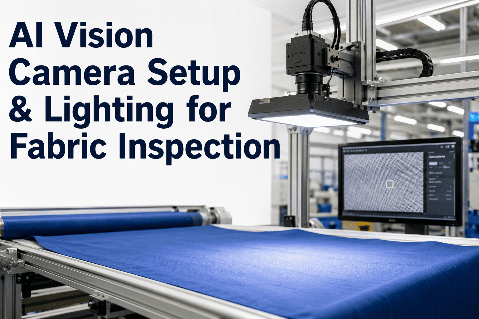
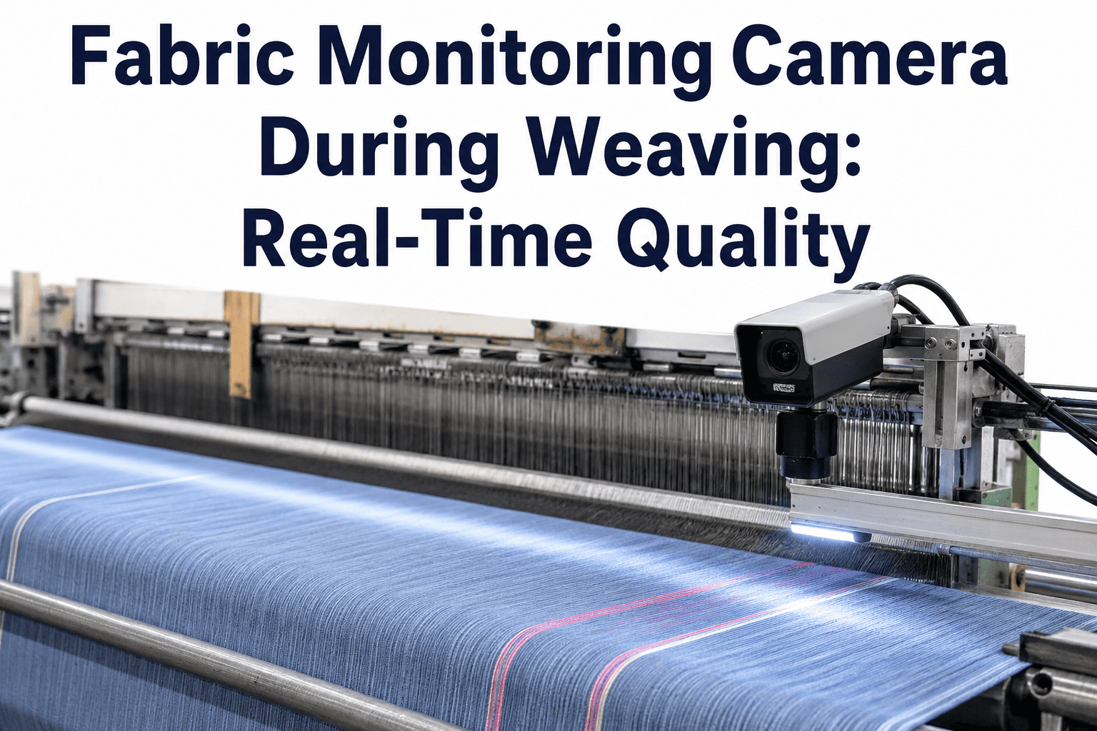
A deep learning model with state-of-the-art accuracy is worthless if the camera feeding it cannot resolve the defects it needs to classify, or if the lighting configuration creates specular glare that washes out exactly the texture variation the model was trained to detect. Camera and lighting selection for fabric inspection is not a generic machine vision problem — fabric has optical properties that differ meaningfully from the rigid, matte, single-material objects that dominate typical industrial vision applications. Woven and knitted structures produce different reflection characteristics, fabric moves continuously at production speed rather than sitting still for inspection, and defect sizes range from sub-millimeter texture anomalies to full-width bars — each demanding different resolution and lighting decisions. Getting the hardware layer right is the prerequisite that determines whether even a well-trained AI model can actually see what it needs to see. Book a session with the iFactory vision systems team to review camera and lighting specification for your specific fabric types and line configuration.
Manual Inspection · Vision Hardware Specification
AI Vision Camera Setup and Lighting Design for Inline Fabric Inspection
Camera resolution, frame rate, field-of-view geometry, and lighting configuration specific to woven and knitted fabric optical properties — the physical hardware layer that determines whether your AI model can actually see the defects it was trained to detect.
30 m/min line speed, 0.15mm/pixel resolution target → 500 mm/s ÷ 0.15 mm/pixel ≈ 3,333 Hz line rate required
Resolution and Frame Rate Calculation
Matching Camera Specification to Defect Size and Line Speed — the Foundational Calculation
Every camera and lighting decision downstream depends on first establishing two numbers correctly: the spatial resolution (millimeters per pixel) needed to reliably detect the smallest defect in your catalog, and the acquisition rate needed to sustain that resolution at your actual production line speed. Getting either number wrong either produces a camera specification that cannot see small defects, or one that generates more data than the downstream processing pipeline can handle.
01
Determine Minimum Detectable Defect Size
Establish the smallest defect from your catalog that must be reliably detected — for fabric inspection this is often a fine warp streak or a single broken filament, commonly in the 0.2 to 0.5mm range. The Nyquist sampling principle requires at minimum 2 pixels across the smallest feature to be detectable at all, but reliable classification (not just detection) typically requires 4 to 8 pixels across the minimum defect dimension.
02
Calculate Required Spatial Resolution
Required resolution (mm/pixel) = Minimum defect size ÷ Minimum pixels across defect. For a 0.3mm defect requiring 5 pixels across for reliable classification: 0.3mm ÷ 5 = 0.06mm/pixel resolution target — this becomes the design constraint for sensor selection and field-of-view configuration.
03
Calculate Sensor Resolution from FOV and Target Spatial Resolution
Required sensor pixel count (across width) = Field of view width ÷ Spatial resolution target. For a 1,800mm fabric width at 0.06mm/pixel resolution: 1,800 ÷ 0.06 = 30,000 pixels required across the fabric width — this determines whether a single line-scan camera can cover the full width or whether multiple cameras must be tiled across the width.
04
Calculate Required Line Rate from Line Speed
Required line rate (Hz) = Line speed (mm/s) ÷ Along-web resolution (mm/pixel), matching the along-web pixel pitch to the same spatial resolution target used across the width for square (isotropic) pixels. At 30 m/min (500mm/s) and 0.06mm/pixel: 500 ÷ 0.06 ≈ 8,333 Hz — this line rate, combined with sensor width, determines the required camera and interface bandwidth (Camera Link, CoaXPress, or GigE Vision).
Camera Type Selection
Line-Scan vs. Area-Scan — Which Fits Continuous Fabric Web Inspection
The choice between line-scan and area-scan camera technology is the first major architectural decision in fabric vision system design, and for continuous web inspection at production speed, the answer is usually clear-cut in favor of one technology — but understanding why matters for edge cases and multi-camera configurations.
Characteristic
Line-Scan Camera
Area-Scan Camera
Image acquisition
Single pixel row per trigger, builds 2D image from continuous web motion
Full 2D frame captured simultaneously
Motion handling
Purpose-built for continuous web motion — no motion blur if line rate matched to speed
Requires strobed lighting or high shutter speed to freeze motion; risk of blur at high line speed
Resolution across width
Very high — sensors up to 16K+ pixels available in a single line
Limited by sensor size; wide FOV coverage requires more cameras or lower resolution
Continuous coverage
Native — every millimeter of fabric length is captured with no gaps
Requires careful frame rate and FOV overlap calculation to avoid gaps between frames
Typical use case
Primary technology for continuous fabric web inspection at production speed
Line-scan cameras are the standard choice for primary full-width fabric inspection given their native fit to continuous web motion and superior width resolution. Area-scan cameras retain a valuable secondary role for dedicated selvage inspection (where higher magnification of a narrow zone is needed) or for defect confirmation imaging at reduced line speed during quality investigation.
Lighting Physics for Fabric
Why Woven and Knitted Fabric Require Different Lighting Approaches
Fabric's optical behavior under illumination differs fundamentally from most industrial inspection targets because fabric surfaces combine specular reflection (from fiber and yarn surfaces), diffuse scattering (from the fiber matrix), and — critically for defect detection — shadow-casting texture at the yarn and weave/knit structure scale. The lighting configuration must be designed around which optical behavior best reveals the defect types being targeted.
Diffuse Dome / Cloud Lighting
Even, omnidirectional illumination eliminates directional shadows and specular hotspots, revealing color and shade uniformity clearly. Best for detecting shade variation, weft bars, and dye-related defects where the concern is color/tone consistency rather than surface texture. Poor at revealing subtle surface texture defects since it actively suppresses the shadow contrast that reveals them.
Low-Angle Raking Light
Light striking the fabric surface at a shallow angle (typically 10–30 degrees from the fabric plane) casts pronounced shadows from any surface irregularity — yarn snarls, reed marks, weave structure faults, and surface unevenness become highly visible through the shadow pattern they cast. The essential technique for surface-relief defects that diffuse lighting would suppress.
Backlighting / Transmitted Light
Light source positioned behind the fabric, transmitted through the material to the camera on the opposite side. Highly effective for detecting holes, thin spots, missing yarns, and density variation — defects defined by how much light passes through rather than how light reflects off the surface. Requires physical access to both sides of the fabric web, a configuration constraint not all inspection points can accommodate.
Structured / Multi-Angle Illumination
Sequential or simultaneous illumination from multiple discrete angles, sometimes combined with polarization filtering to separate specular from diffuse reflection components. Provides the richest defect signal by combining the strengths of raking light (texture/relief) and diffuse light (color/tone) but adds hardware complexity and cost — typically reserved for high-value fabric segments where maximum detection accuracy justifies the investment.
Get Your Camera and Lighting Configuration Specified
iFactory's Vision Systems Team Calculates Resolution, Frame Rate, and Lighting Configuration for Your Specific Fabric and Line Speed
Generic camera and lighting recommendations rarely fit a specific fabric type, defect catalog, and line speed combination. iFactory's vision hardware assessment calculates the exact resolution and frame rate requirements for your defect catalog and specifies the lighting configuration matched to your fabric's optical characteristics.
Woven vs. Knitted Fabric — Different Structures, Different Optimal Configurations
Woven and knitted fabric present meaningfully different optical challenges due to their structural differences — woven fabric's rigid, orthogonal yarn crossing pattern behaves differently under directional lighting than knitted fabric's interlocking loop structure, which has more three-dimensional surface relief and typically higher elasticity affecting web tension and flatness at the inspection point.
Woven Fabric Configuration
Primary: Low-angle raking light (15–20°) for warp/weft defect detection — the orthogonal grid structure creates strong, consistent shadow patterns under raking illumination
Secondary: Diffuse overhead lighting for shade and color consistency evaluation, run as a second inspection pass or dual-camera configuration
Consider: Backlighting supplementary station for hole and thin-spot detection, particularly valuable for lighter-weight woven fabrics
Knitted Fabric Configuration
Primary: Diffuse dome lighting as the base configuration — knitted fabric's inherent three-dimensional loop structure creates natural texture visibility even under even illumination, reducing the need for aggressive raking angles
Secondary: Moderate-angle directional light (30–45°) to reveal dropped stitches, snags, and loop irregularities without over-emphasizing normal structural texture into false-positive noise
Consider: Tension and web flatness at the inspection point matters more for knitted fabric given higher elasticity — lighting geometry calculations must account for potential web flutter affecting working distance consistency
Integration Checklist
Physical Installation Considerations Beyond Camera and Light Selection
Camera and lighting selection is necessary but not sufficient — physical integration factors determine whether the theoretically correct hardware specification actually performs as designed once installed on a production line.
Working Distance and Depth of Field
Fabric web flutter, tension variation, and roll diameter changes (for roll-to-roll configurations) all introduce working distance variation the lens must accommodate within its depth of field, or the system risks focus drift. Confirm the actual expected working distance range at the specific inspection point, not just the nominal design value.
Ambient Light Contamination
Factory floor ambient lighting, sunlight through windows, or adjacent process illumination can contaminate the controlled lighting configuration, particularly for diffuse and low-angle raking setups sensitive to directional light sources. Physical shrouding or enclosure around the inspection point is often necessary, not optional, for lighting consistency.
Vibration and Mounting Rigidity
Line-scan cameras operating at high resolution are sensitive to mechanical vibration, which manifests as image smear or banding artifacts. Mounting structures must be rigid and isolated from vibration sources (motors, drives, mechanical actuators) common in a production environment.
Dust, Lint, and Fiber Contamination
Textile production environments generate significant airborne lint and fiber debris that accumulates on lens surfaces and light source housings, gradually degrading image quality if not addressed. Enclosure design should include accessible cleaning points and, where feasible, positive air pressure or air-knife protection for lens and lighting surfaces.
Vision Hardware KPIs
Six Metrics That Confirm Your Vision Hardware Is Correctly Specified and Maintained
Effective Spatial Resolution
Target: matches design specification
Verified achieved resolution (mm/pixel) under actual production conditions, confirmed via a calibration target — distinct from the theoretical resolution calculated from sensor and lens specifications, which can differ due to lens distortion, focus accuracy, or working distance variance.
Illumination Uniformity
Target: <10% variance across FOV
Variation in light intensity across the full field of view width, measured via a calibration reference. Excessive variance (bright center, dim edges, common with poorly designed line lighting) causes inconsistent defect visibility across the fabric width and inconsistent model confidence.
Motion Blur / Smear Rate
Target: 0% at rated line speed
Percentage of captured frames showing motion artifacts at maximum rated production line speed. Any non-zero rate at rated speed indicates line rate, exposure time, or lighting intensity is mismatched to actual production speed and requires reconfiguration.
Lens/Lighting Fouling Interval
Target: >7 days between cleaning
Time between required cleaning cycles for lens and lighting surfaces due to lint/fiber accumulation. Short intervals indicate insufficient environmental protection in the enclosure design and predict increasing image quality degradation risk between scheduled maintenance.
Focus Drift Frequency
Target: <1 event/month
Frequency of detected focus quality degradation requiring manual or automated refocus intervention. Rising frequency often indicates mounting vibration issues or working distance variability exceeding the lens depth of field design margin.
Ambient Light Contamination Events
Target: 0 per shift
Occurrences of image quality anomalies traceable to uncontrolled ambient light sources (sunlight changes, adjacent process lighting). Should be zero with proper shrouding — any detected events indicate an enclosure or shielding gap requiring physical remediation.
From the Systems Integration Floor
“
Every fabric inspection project I have integrated over the past fifteen years has the same failure pattern waiting to happen if the hardware layer is treated as an afterthought to the AI model. I have watched teams spend months tuning a deep learning model's hyperparameters to squeeze out another percentage point of validation accuracy, while the camera resolution installed on the actual production line was physically incapable of resolving half the defect types in their own catalog — no amount of model tuning fixes a resolution deficit, because the information the model needs was never captured in the image to begin with. The lighting side is even more commonly underinvested. I still regularly see systems specified with a single diffuse light source trying to do the job of both texture detection and color evaluation simultaneously, when the physics of the problem genuinely requires different illumination geometry for those two tasks. Getting the camera and lighting specification right before writing a single line of model training code is not a nice-to-have step — it is the step that determines the ceiling on what any subsequent AI model can possibly achieve, no matter how sophisticated the architecture or how well the training data is curated.
Henrik Adeyinka-Larsson
Machine Vision Systems Integrator · Industrial Automation Engineer · 15 years specifying and deploying vision hardware for textile and manufacturing inspection · Former Lead Vision Engineer, European machine vision integration firm · Specialist in line-scan camera systems and structured lighting design
Systems Integration Questions
AI Vision Camera Setup and Lighting for Fabric Inspection — Frequently Asked
Can we use a single lighting configuration to detect both texture defects and color/shade defects, or do we always need multiple lighting setups?
In most cases, effective detection of both defect categories requires either two distinct lighting configurations (commonly implemented as sequential dual-camera stations, one with raking light and one with diffuse light) or a more sophisticated structured/multi-angle lighting system that captures both signal types simultaneously through polarization separation or sequential strobing. A single conventional diffuse or single-angle lighting setup will always compromise one detection category to serve the other — diffuse lighting suppresses the shadow contrast texture defects need, while raking light introduces shadow patterns that can obscure subtle color variation. For fabric segments where both defect categories carry meaningful commercial risk (most apparel and home textile applications), budget for a dual-configuration or structured lighting approach rather than attempting to compromise with a single setup. For lower-risk technical textile applications where one defect category dominates commercial concern, a single optimized configuration targeting that category may be sufficient. For a lighting configuration recommendation specific to your defect priority profile, book a session with the iFactory vision systems team.
How do we handle very wide fabric (over 3 meters) where a single line-scan camera cannot achieve the required resolution across the full width?
Wide fabric inspection at high resolution typically requires tiling multiple line-scan cameras across the width, each covering a defined sub-section of the total fabric width with a small overlap zone between adjacent camera fields of view to ensure no gap exists at the tile boundaries. The overlap zone (typically 2 to 5% of each camera's field of view) requires either stitching the images into a single continuous frame in software, or running defect detection independently on each camera's feed with logic to prevent double-counting defects that happen to fall within the overlap region. Camera synchronization (ensuring all tiled cameras trigger at precisely the same web position) is critical for successful image stitching and requires either hardware-triggered synchronization from a shared encoder signal or precise software-level timestamp alignment. The number of cameras required scales directly with total fabric width divided by the width each camera can cover at the target resolution — a 4-meter fabric requiring 0.06mm/pixel resolution with cameras offering 16K pixel line sensors (covering approximately 960mm at that resolution) would require a minimum of 5 tiled cameras with appropriate overlap. Contact our support team for a multi-camera tiling design specific to your fabric width and resolution requirements.
What is the practical difference between GigE Vision, CoaXPress, and Camera Link interfaces for high-speed line-scan cameras, and which should we choose?
The interface choice is determined primarily by the required data bandwidth, which depends on line rate, sensor width, and bit depth. GigE Vision (1G or the newer 5/10G variants) offers the simplest cabling and longest cable run distances but has bandwidth limitations that constrain it to lower line rates or narrower/lower-resolution sensors — generally suitable for line rates up to a few kHz depending on sensor width and the specific GigE variant. CoaXPress offers substantially higher bandwidth (up to 12.5 Gbps per connection, with multi-connection configurations available for even higher throughput) over a single coaxial cable with long cable run capability, making it the current standard choice for high-resolution, high-line-rate fabric inspection applications. Camera Link, while historically dominant and still supported by many camera manufacturers, has largely been superseded by CoaXPress for new installations due to CoaXPress's superior cable length capability and simpler cabling for high-bandwidth configurations, though Camera Link remains a valid choice where existing frame grabber infrastructure is already in place. For most new fabric inspection line-scan camera deployments requiring the resolution and line rate calculations described earlier in this reference, CoaXPress is the recommended default interface choice.
How do we prevent lighting configuration drift over time as LED light sources age and degrade in intensity?
LED light source intensity degrades gradually over operating hours — typically losing 10 to 30% of initial output over 20,000 to 50,000 operating hours depending on the specific LED technology, drive current, and thermal management design — and this gradual drift can silently degrade image quality and model performance well before triggering an obvious failure. The primary mitigation is active light intensity feedback and compensation: many industrial machine vision lighting controllers support closed-loop intensity monitoring via a reference photodiode, automatically increasing drive current to compensate for degradation and maintaining consistent output over the light's operational life until it reaches end-of-life replacement threshold. Where active compensation is not available, a scheduled calibration and verification protocol — periodically checking illumination uniformity and intensity against the original calibration baseline using a reference target — catches drift before it silently degrades detection accuracy, with light source replacement scheduled proactively based on measured degradation trend rather than waiting for a visible failure. Building this monitoring into the broader vision system health monitoring (alongside the KPIs discussed earlier) ensures lighting drift is caught as part of routine operations rather than requiring a separate, easily-forgotten maintenance task.
Should the camera and lighting system be specified before or after the AI model architecture and training approach is finalized?
Camera and lighting specification should generally be finalized before extensive model training investment, because the hardware determines the ceiling on image quality and information content available to any model — a model cannot learn to detect a defect signature that the camera and lighting configuration never captured with sufficient fidelity. The recommended sequence starts with defect catalog definition (establishing what must be detected and at what minimum size), followed by camera and lighting specification calculated against that catalog's requirements, followed by initial data collection using the finalized (or near-final) hardware configuration, and only then substantial model training investment using data genuinely representative of the production hardware. Training extensively on data captured with placeholder or preliminary hardware, then discovering the production hardware configuration differs meaningfully, risks requiring substantial retraining once real production-representative data becomes available — a costly rework that proper sequencing avoids. Book a project sequencing consultation with the iFactory team to plan your specific implementation timeline.
The AI Model Can Only See What the Camera and Lighting Capture
Get Your Camera Resolution, Frame Rate, and Lighting Configuration Specified for Your Actual Fabric and Line Speed
iFactory's vision systems team calculates the exact resolution and frame rate requirements for your defect catalog, specifies line-scan or area-scan camera configuration matched to your line speed, and designs the lighting geometry appropriate to your woven or knitted fabric structure — the hardware foundation that determines what any downstream AI model can actually achieve.