Stenter frames sit at the center of nearly every fabric finishing line, yet they remain one of the most under-monitored machines on the production floor. A one-degree drift in zone temperature or a half-millimeter shift in pin spacing can quietly push finished fabric outside its width and shrinkage tolerance, triggering costly rework, customer claims, and second-quality markdowns days after the roll has already left the stenter. For textile plant managers and finishing floor supervisors, the challenge is rarely knowing that stenter parameters matter — it is catching drift in real time, before an entire batch runs out of specification. This guide walks through the operating variables that actually control width, shrinkage, and GSM outcomes, and shows how continuous monitoring changes the economics of stenter operation, a workflow detailed further in iFactory's support resources for finishing floor teams.
01 / Why Stenter Frames Are the Most Expensive Blind Spot in Finishing
A stenter frame does three jobs at once — it sets fabric width, drives shrinkage down to a target percentage, and locks in GSM within a contractual tolerance. Because these three outcomes are produced by the same pass through the machine, a small error in one zone rarely shows up as a single defect. Instead it shows up as a batch that measures correctly at the headstock and drifts out of tolerance three hundred meters later, once temperature has crept up, chain tension has relaxed, or overfeed has been nudged by an operator trying to compensate for a different fault. Most finishing floors still rely on periodic manual spot-checks with a tape measure and a GSM cutter, which means drift is frequently caught only after a meaningful length of fabric has already run out of specification.
02 / Inside the Zones — Temperature, Drying, and Cure Progression
A typical six-zone stenter takes fabric through a deliberate temperature progression, and every zone has a distinct job. Getting the ladder wrong in either direction — too aggressive early, too weak late — is one of the most common causes of uneven heat-set and inconsistent shrinkage across a single roll. The zone ladder below reflects a representative profile for a polyester-cotton blend; exact ranges shift with fabric construction, finish chemistry, and line speed, but the sequencing logic holds across most fabric types.
03 / Width, Overfeed, and Chain Speed — The Three Levers Operators Actually Control
Operators cannot directly set shrinkage or GSM — those are outcomes. What they set is width (via pin-to-pin rail spacing), overfeed percentage, and chain dwell time, and these three levers interact in ways that make manual tuning genuinely difficult without live feedback.
| Parameter | What It Controls | Typical Range | Risk If Mismanaged |
|---|---|---|---|
| Width Setting | Final fabric width and cross-directional shrinkage | Fabric-specific, set at pin rail entry | Off-width rolls rejected at cut-and-sew or garment stage |
| Overfeed Percentage | Length-wise shrinkage and GSM buildup | 3-12% depending on fabric construction | GSM falls outside buyer tolerance, triggering claims |
| Chain Dwell Time | Degree of heat-set completion in each zone | Set via line speed relative to zone length | Incomplete cure leads to relaxation shrinkage after dispatch |
| Zone Temperature | Rate and completeness of dimensional stabilization | Profile-specific, see zone ladder above | Uneven heat-set across roll width, streaky handfeel |
04 / Chain Pin Spacing and Fabric Tracking
Beyond temperature and overfeed, the pin chain itself is a frequent and under-diagnosed source of width variation. Expand each item below for what typically goes wrong and how it shows up on finished fabric.
Pin spacing calibration drift
Pin rails are calibrated to a fixed spacing at installation, but wear on the pin chain, guide rail, and drive sprockets gradually changes effective spacing over months of operation. This shows up as width creeping narrower or wider across production runs even though the operator has not touched the width setting. Recalibration on a fixed schedule catches this, but continuous width measurement at the exit stenter catches it as it happens rather than at the next scheduled check.
Selvedge damage from pin penetration
Pins that penetrate too deep or at an incorrect angle damage the fabric selvedge, creating pin holes that become a quality claim at inspection. This is most common on lightweight and delicate fabrics where pin pressure needs to be set lower than the standard machine default. Selvedge condition should be checked at the start of every fabric-type changeover, not only during scheduled maintenance windows.
Tracking drift and bow or skew
Uneven tension between the left and right pin chains causes fabric to track off-center, producing bow or skew that distorts printed and woven patterns. This is one of the harder faults to catch by eye on a fast-moving line, and it typically requires either a trained operator watching the selvedge line continuously or a vision-based tracking sensor feeding an alert when deviation exceeds a set threshold.
05 / Real-Time Stenter Monitoring With iFactory
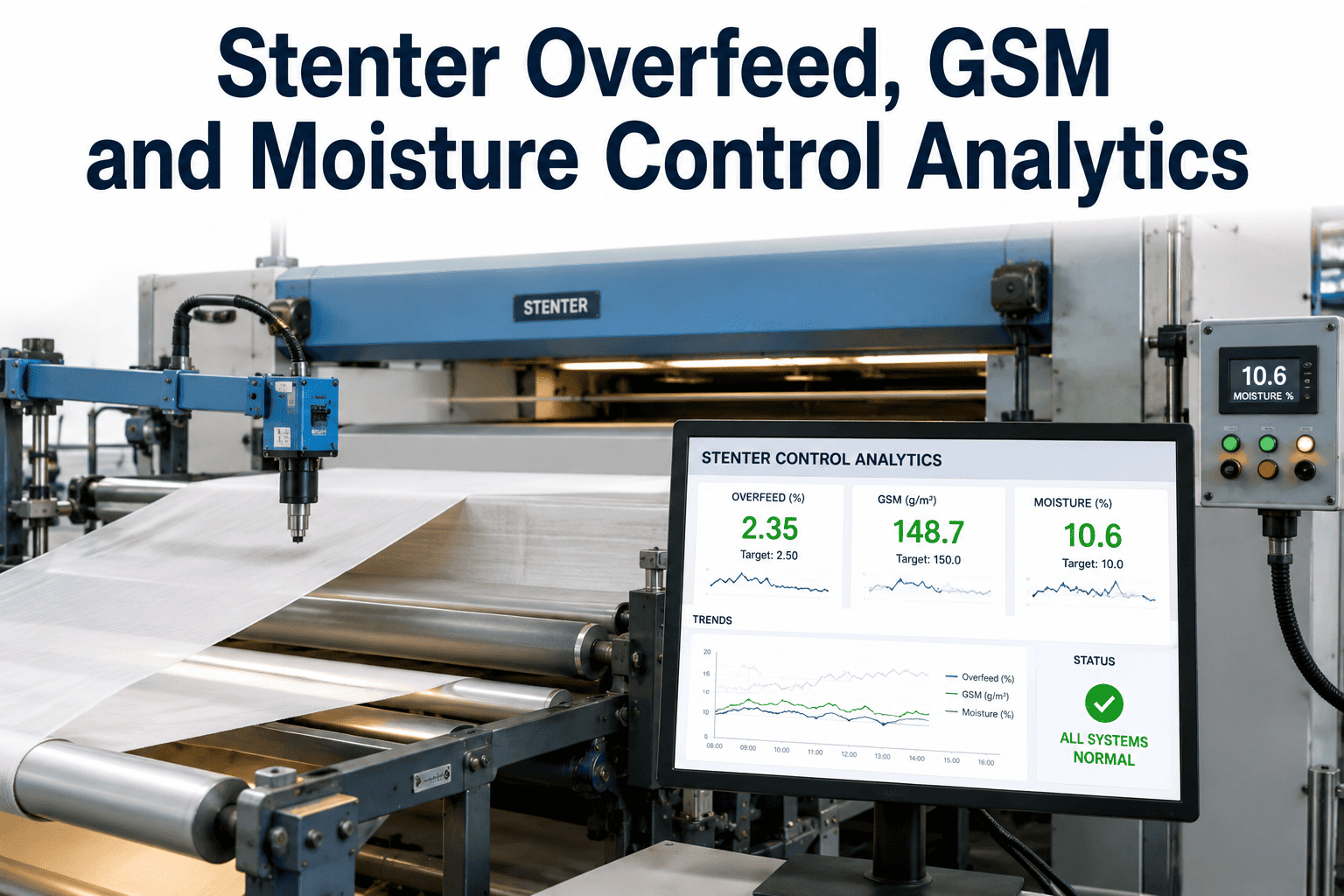
Continuous monitoring does not replace the operator's judgment — it gives them a live picture of the same parameters they are already managing, updated every few seconds instead of every few hours.
06 / Getting From Manual Checks to Continuous Monitoring
Adding monitoring to an existing stenter line is a phased process rather than a machine replacement, and most finishing floors move through it in three stages.
Conclusion — Precision Stenter Operation Starts With Visibility
Width, shrinkage, and GSM are not separate problems — they are three readings of the same heat-set process, and the finishing floors that manage them well are the ones with continuous visibility into zone temperature, chain tracking, and exit measurements rather than periodic spot-checks. Book a demo to see how iFactory's monitoring platform maps onto your existing stenter configuration and fabric portfolio.
Frequently Asked Questions — Stenter Frame Operation
Width variation with an unchanged setting is almost always mechanical rather than a deliberate parameter change. Pin chain wear, guide rail wear, and sprocket drift all gradually alter the effective distance between pin rails over months of operation, so the machine drifts away from its calibrated width without any operator input. Fabric shrinkage behavior can also shift if a supplier changes yarn or finish chemistry between lots, which changes how much the fabric relaxes at a given temperature and overfeed setting even though the stenter itself is unchanged. The most reliable way to separate mechanical drift from fabric-driven variation is continuous exit-width measurement correlated against fabric batch identifiers, which is covered in more detail in iFactory's support documentation.
Acceptable shrinkage tolerance depends heavily on the end use and buyer specification, but most woven and knit fabrics for apparel are held to a tolerance band of plus or minus one to two percent from the target shrinkage figure agreed with the buyer. Technical and industrial fabrics, particularly those used in automotive or filtration applications, often carry tighter tolerances given downstream dimensional requirements. Deviations beyond the agreed band typically trigger a quality hold and retest, and repeated deviations on the same fabric construction usually point to a zone temperature or overfeed issue rather than a one-off fault, which is why tracking deviation trends over time matters more than any single test result.
Continuous monitoring reduces pin-related damage primarily by catching tracking drift and tension imbalance early, before pin penetration angle or depth becomes severe enough to tear the selvedge. Vision-based tracking sensors watching the selvedge line in real time can flag bow, skew, or edge lift within seconds, well before an operator doing periodic walk-throughs would notice the same drift. It does not eliminate the need for physical pin maintenance and periodic replacement, but it does shrink the window between a mechanical fault developing and someone acting on it, which is usually where the bulk of avoidable selvedge damage occurs on a finishing line.
Overfeed feeds fabric into the stenter faster than the pin chain is moving, allowing the fabric to relax lengthwise as it heat-sets, which increases fabric density and therefore GSM. Higher overfeed generally produces higher GSM and lower lengthwise shrinkage after washing, while lower overfeed produces the opposite. The relationship is not perfectly linear across all fabric constructions, however, which is why correlating overfeed against actual downstream GSM test results for a specific fabric is more reliable than applying a generic industry rule of thumb across an entire product range.
Most deployments on an existing stenter line move through baseline data capture, sensor installation, and threshold configuration within four to eight weeks, depending on how many zones and sensor points are being instrumented and whether the line already has any temperature or width sensing infrastructure in place. The baseline capture phase generally takes the longest because it needs to span multiple fabric constructions to build tolerance thresholds that reflect real production variation rather than a single run. Book a demo to get a deployment timeline scoped against your specific stenter configuration.