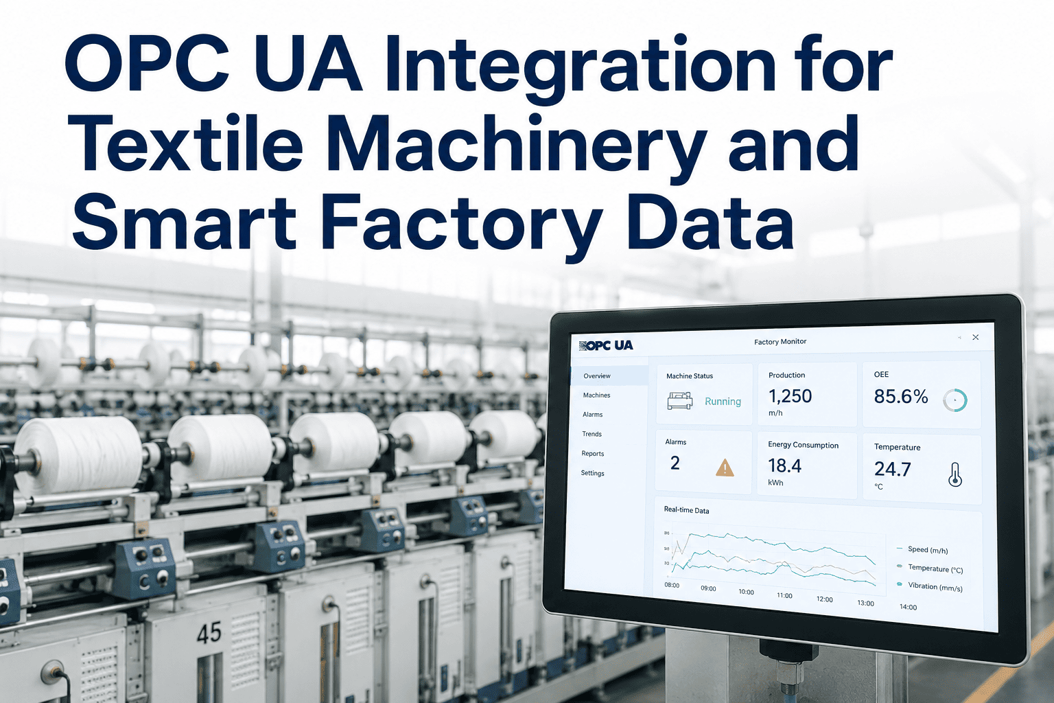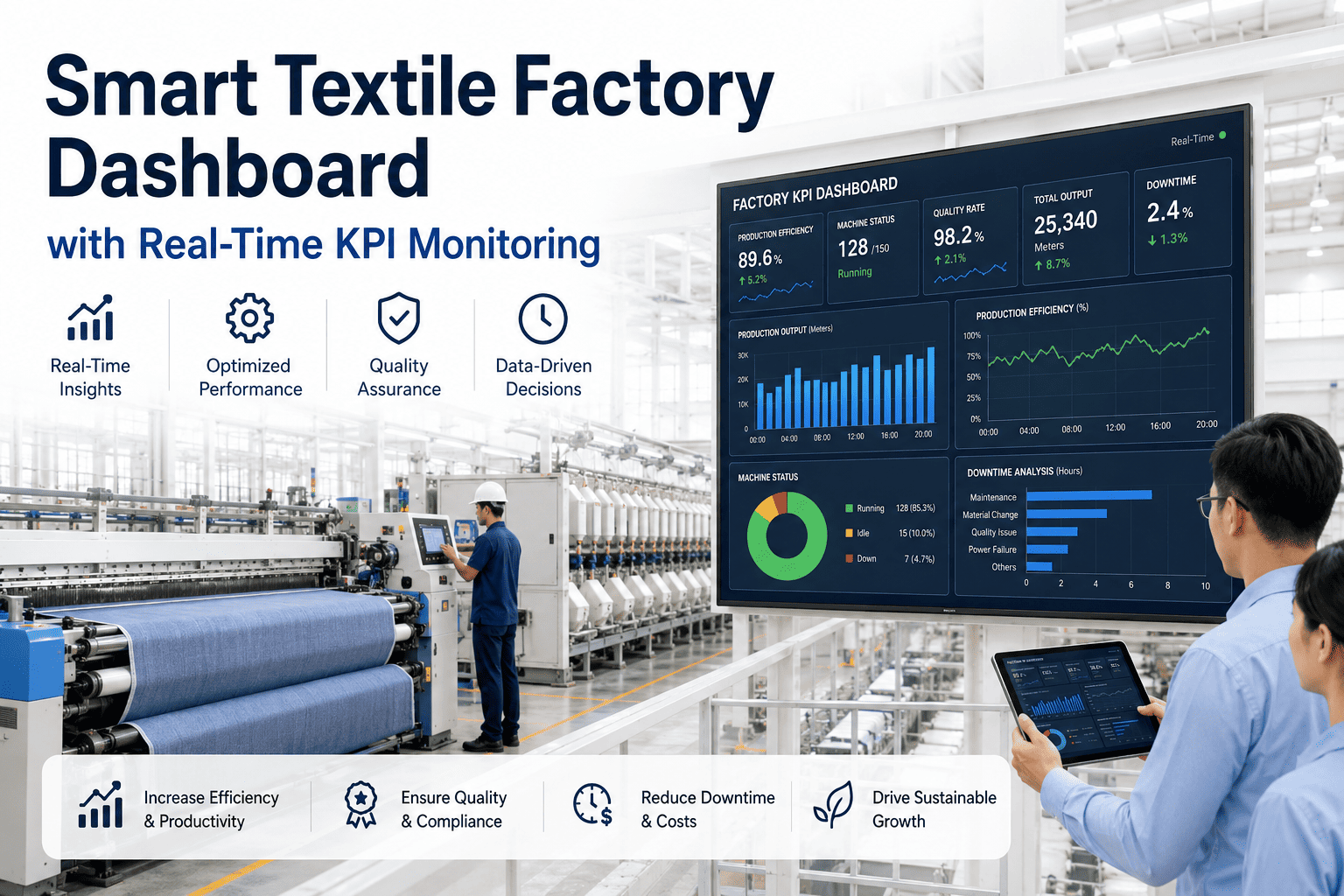
A spinning machine that cannot share its data has no way to contribute to production analysis, quality traceability, or predictive maintenance. Most textile mills have machines with controllers that hold exactly the data needed — yarn break counts, motor temperatures, speed signals, dyeing temperature profiles — but no structured path to get that data into a system where it can be acted on. SCADA and PLC integration is what builds that path, turning isolated machine intelligence into a connected operational picture. The scope, protocol choices, and sequencing of an integration project determine whether the result is a stable data foundation or a maintenance burden. Teams planning this for their mill can discuss their integration architecture with iFactory AI's textile engineering team.
Connect Your Spinning Frames, Stenter, and Dyeing Machines to One Live Data Layer
iFactory AI integrates with PLC and SCADA systems across spinning, stenter and dyeing assets using OPC-UA, Modbus, MQTT, and BMS protocols — capturing machine, process, quality and energy signals in connected textile workflows.
What Does SCADA and PLC Integration Mean for a Textile Mill?
SCADA (Supervisory Control and Data Acquisition) systems in textile mills traditionally serve a monitoring and control function at machine or department level — they read sensor data, display it locally, and may trigger alarms. PLC (Programmable Logic Controller) integration means extracting the operational data already captured by machine controllers and routing it to a higher-level analytics or MES platform.
Spinning Machine Integration: What Data Matters and How to Get It
Ring spinning machines are the core data source for yarn quality and production analytics. Modern ring frames from leading OEMs (Rieter, Lakshmi Machine Works, Truetzschler) have PLCs that expose data through OPC-UA or proprietary interfaces. Older machines may require a PLC gateway retrofit to make their data available.
For machines without native OPC-UA output, iFactory AI supports Modbus RTU/TCP polling as well as gateway devices that read machine-specific serial protocols and translate them to a standard format. Ask the iFactory AI team which gateway works for your specific ring frame model.
Map the Integration Architecture for Your Spinning Department
iFactory AI's engineering team will design the PLC integration path for your specific ring frame models — including protocol, gateway hardware, and data signal scope — before deployment.
Stenter SCADA Integration: Temperature, Speed, and Energy
The stenter is the highest energy consumer in most finishing departments, and its process parameters — zone temperatures, fabric speed, overfeed — directly determine shrinkage, GSM, and dimensional stability of finished fabric. Stenter SCADA integration connects these process signals to iFactory AI's energy monitoring and quality analytics modules.
| Signal | Protocol | What iFactory AI does with it |
|---|---|---|
| Zone temperature setpoint vs actual | OPC-UA / Modbus | Deviation alert when actual falls more than 5°C below setpoint; temperature stability trending |
| Fabric speed (m/min) | OPC-UA | Production rate calculation; speed × width = m² throughput; link to energy per m² |
| Gas consumption (m³/hr per zone) | Pulse meter → MQTT | GJ per kg calculation; zone-level gas efficiency; idle gas waste detection |
| Electrical kWh (blower, drive) | Energy meter → MQTT | Total stenter kWh/kg; combined gas + electrical energy intensity |
| Overfeed percentage | OPC-UA | Link overfeed setting to fabric shrinkage test results; recipe compliance check |
| Exhaust temperature | Analog sensor → Modbus | Waste heat recovery opportunity detection; exhaust anomaly alert |
Dyeing Machine BMS Integration: Temperature, Batch, and RFT
Dyeing machine BMS (Batch Management Systems) from Datacolor, Lawer, ProMinent, and similar suppliers hold the most valuable quality data in a dyehouse — the full temperature-time profile of every batch. This data is critical for RFT root cause analysis but is rarely connected to quality management systems. iFactory AI bridges this gap.
Teams running Datacolor or Lawer dispensing systems can ask the iFactory AI support team about the specific integration path for their BMS supplier.
Protocol Selection Guide for Textile Machine Integration
Choosing the right protocol for each machine type determines integration stability, data latency, and maintenance overhead. The table below maps common textile machines to their preferred integration protocol and fallback option.
| Machine type | Preferred protocol | Fallback / alternative | Latency |
|---|---|---|---|
| Ring frame (modern OEM) | OPC-UA | Modbus TCP / serial RS-485 | <1 second |
| Ring frame (older, non-OPC) | Modbus RTU via gateway | Serial data logger + MQTT | 1–5 seconds |
| Draw frame / autoleveller | Proprietary serial + adapter | Modbus TCP | 1–5 seconds |
| Stenter (Brückner, Monforts) | OPC-UA or Modbus TCP | SCADA data export (OPC-DA bridge) | <2 seconds |
| Dyeing BMS (Datacolor, Lawer) | REST API / file-based export | ODBC database connection | Batch-end (near real-time) |
| Energy meters | MQTT over LAN | Modbus TCP polling | <1 second |
| Boiler PLC | Modbus TCP | OPC-UA where available | <5 seconds |
Frequently Asked Questions
Can older ring frame PLCs be integrated without replacing the machine controller?
Yes, in almost all cases. Older ring frames with legacy PLCs (Siemens S5, Allen-Bradley SLC, or proprietary textile OEM controllers) can be connected through a protocol gateway device that reads the machine's existing communication interface and translates it to Modbus TCP or MQTT for iFactory AI. No change is made to the machine controller, so production is not disrupted during installation. The gateway sits between the PLC and the network. Book a session to review the gateway options for your specific ring frame models.
What network infrastructure does a textile PLC integration project require?
A flat Ethernet network reaching every machine group, or a segmented OT network with a managed switch at each spinning section, is the standard requirement. iFactory AI deploys with IT/OT network separation — the OT network carrying machine data is kept separate from the corporate IT network for security. iFactory AI's Greenfield Consulting team designs and supervises the network cabling and switch configuration as part of the deployment scope. Ask about network design requirements for a textile deployment.
How is dyeing BMS data linked to quality management records in iFactory AI?
iFactory AI uses the batch ID as the common key — the BMS records process data against the batch ID, and the laboratory records shade assessment results against the same ID. Once both streams are connected, iFactory AI automatically joins them so every RFT failure has its full process parameter history attached. This linkage eliminates the manual search that most dyehouse quality teams currently perform when investigating a re-dyeing event. See the BMS-to-QMS linkage in action in a live walkthrough.
Does PLC integration require internet connectivity or cloud access?
No. iFactory AI is deployed entirely on-premise on an NVIDIA GPU server inside the mill — all PLC data is processed, stored, and analysed locally. There is no dependency on cloud connectivity for any operational function. This is a critical requirement for mills in locations with unreliable internet, or for mills with data sovereignty policies that prohibit process data leaving the site. Ask about iFactory AI's on-premise deployment model and data handling.
What is the typical integration timeline for a 20,000-spindle spinning mill with dyeing?
A 20,000-spindle mill with spinning and dyeing typically completes the core integration in Weeks 1–8 of iFactory AI's standard deployment: network cabling and switch configuration in Weeks 1–2, ring frame PLC connections and energy meter installation in Weeks 3–5, dyeing BMS integration and Uster data feed in Weeks 5–8, and dashboard configuration and operator training in Weeks 9–12. Full go-live with all dashboards and alerts active occurs within the 6–12 week window. Book a session to discuss the deployment timeline for your specific mill configuration.
Connect Your Spinning, Stenter and Dyeing Data to One Live Analytics Layer
iFactory AI integrates with every machine type in your textile mill — on-premise, no cloud dependency, with dedicated engineering support through the full integration scope.