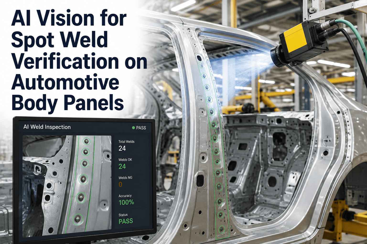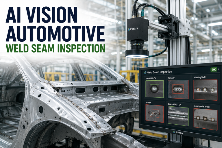
Weld quality in automotive body-in-white manufacturing is one of the highest-stakes inspection challenges on the production floor. A modern vehicle body carries between 3,000 and 5,000 resistance spot welds, plus continuous seam welds at structural joints, and every one of those welds must meet IATF 16949 structural integrity requirements before the body advances to paint and assembly. The failure mode that makes this so difficult is not that weld defects are rare — porosity, spatter, missing nuggets, incomplete fusion, and undercut occur regularly as electrode wear progresses, shielding gas pressure drifts, and fixturing tolerances accumulate across high-volume production shifts. The failure mode is that conventional inspection methods cannot cover every weld at line speed. X-ray sampling audits a fraction of the welds on a fraction of the units. Manual visual inspection misses subsurface porosity entirely and cannot keep pace with robotic welding throughput. The consequence is that a statistically predictable number of structurally compromised welds pass to the next station every shift — invisible until a warranty claim, a crash test anomaly, or a field failure forces a root cause investigation that traces back to a weld the line never verified. iFactory's AI vision defect detection platform resolves this coverage gap by deploying deep learning models that inspect every spot weld and seam weld on the body-in-white in real time, classifying porosity, spatter, missing welds, incomplete fusion, undercut, and geometric deviation against the qualified weld specification — at full production speed, with image evidence and defect classification for every weld on every unit.
Why Automotive Weld Inspection Demands AI Vision
The Coverage Gap That Sampling Programs Cannot Close
The fundamental problem with weld quality assurance on automotive body-in-white lines is not a shortage of inspection effort — it is a structural mismatch between production volume and inspection capacity. Robotic resistance spot welding operates at rates that make 100% manual inspection physically impossible. Destructive testing — peel and chisel testing of spot weld nuggets — verifies weld quality definitively but consumes the part and cannot be performed on production units. X-ray inspection provides subsurface defect visibility but requires removing the body from the line, exposing inspection personnel to radiation hazard, and accepting the inspection time as lost production. The practical result is that most automotive manufacturers perform destructive testing on sacrificial panels at shift start and end, conduct manual visual audits on a statistical sample, and rely on process control of welding parameters — current, time, force, electrode condition — as a proxy for individual weld quality. This approach works when the process is perfectly in control. It fails when an electrode tip begins to degrade mid-shift, when a fixturing clamp wears and allows joint gap variation, or when shielding gas pressure drops incrementally below specification on MIG or TIG operations. These are exactly the failure modes that produce clusters of defective welds between audit points — invisible to sampling, undetected by parameter monitoring alone, and structurally present in vehicles that pass to paint and assembly with no inspection evidence to the contrary. AI vision eliminates this gap by providing continuous, 100% weld coverage that identifies the specific welds with specific defect types on specific units — converting weld quality assurance from a statistical process control exercise into a direct measurement of every weld produced.
Weld Defect Types Detected by iFactory AI Vision
Spot Welds, Seam Welds, and the Full Defect Classification Taxonomy
iFactory AI Vision Inspection Coverage for Automotive Weld Operations
Multi-Modal Detection Across Welding Process Types and Body Structure Zones
| Welding Process | Detectable Defects | Inspection Method | Applicable Standard |
|---|---|---|---|
| Resistance Spot Welding | Missing nugget, undersized nugget, expulsion, electrode wear mark, spatter | Optical + thermal multi-modal fusion, nugget diameter measurement | IATF 16949 / AWS C1.1 / ISO 14373 |
| MIG / MAG Seam Welding | Porosity, undercut, incomplete fusion, spatter, bead geometry deviation | High-resolution optical, 3D profilometry, weld pool thermal | AWS D1.1 / ISO 5817 / EN 1289 |
| Laser Seam Welding | Keyhole porosity, micro-cracks, incomplete fusion, seam gap, surface oxidation | Multi-angle optical, thermal imaging, inline 3D geometry | ISO 13919-1 / AWS D1.1 |
| TIG / GTAW Welding | Porosity, tungsten inclusion, lack of penetration, undercut, oxidation | High-resolution optical, weld zone thermal, post-weld profilometry | AWS D1.1 / ISO 5817 |
| Projection Welding | Missing projection weld, expulsion, cold weld, electrode burn-through | Thermal signature analysis, surface indentation measurement | AWS C1.1 / IATF 16949 |
Multi-Modal Imaging Architecture for Weld Defect Detection
Why Optical Alone Is Insufficient for Structural Weld Quality Assurance
Weld defects distribute across three distinct inspection domains: the weld surface visible to optical cameras, the near-surface zone accessible through thermal imaging of the weld cooling cycle, and the subsurface weld cross-section that requires either destructive testing or correlative predictive models to characterize non-destructively. An inspection system relying solely on optical imaging captures surface porosity, spatter, and gross geometric deviations accurately — but is blind to incomplete fusion, subsurface porosity clusters, and thermal gradient anomalies that indicate weld quality problems below the detection limit of surface imaging. iFactory's weld inspection architecture fuses three imaging modalities at each inspection station: high-resolution optical cameras capturing bead surface morphology, spatter, and geometric profile; thermal cameras positioned to capture the weld zone heat signature during and immediately after the welding cycle, revealing fusion completeness and cooling rate anomalies; and structured light 3D profiling that measures bead geometry against the qualified specification with sub-millimeter accuracy. The AI models that process these multi-modal inputs are trained on metallurgical cross-section data from destructively tested welds, establishing a correlation between surface and thermal appearance and actual structural quality that allows the system to predict subsurface weld integrity from non-destructive measurements. Automotive engineers who want to see this multi-modal detection running on their specific weld joint types and body structure zones can Book a Demo with iFactory's automotive weld inspection team.
Closed-Loop Integration with Body-in-White Production Systems
From Defect Detection to Automatic Work Order and Process Correction
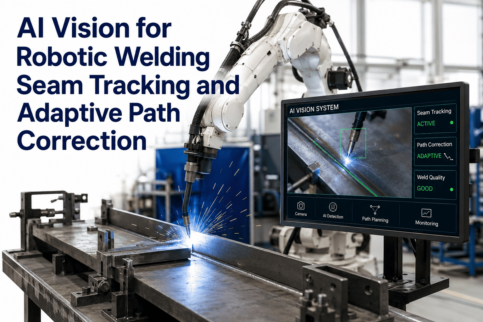
Detecting a weld defect is only valuable if the detection triggers a fast, documented response before the defective body advances further into the production flow. iFactory's weld inspection platform integrates with the body-in-white line's production control system, MES, and CMMS through OPC-UA and REST API connections that convert every defect detection event into a structured response. When the AI model classifies a spot weld as a missing nugget or a seam weld segment as incomplete fusion, the detection event triggers an inline rejection signal to the line's transfer mechanism — holding the body at the current station for rework rather than advancing it to paint with a documented structural defect. Simultaneously, a work order is generated in the CMMS with the defect image, weld location map, defect classification, and severity score attached — providing the rework technician with exact defect location and type information without requiring them to perform a secondary inspection to find the problem. Process trend data from the weld inspection system feeds back to the welding robot's process control parameters through the MES integration layer, enabling adaptive process corrections — electrode dressing cycle initiation, wire feed rate adjustment, shielding gas pressure verification — triggered by the inspection data rather than by scheduled maintenance intervals. Automotive quality and process engineers who want to understand how this closed-loop architecture maps to their specific line configuration are encouraged to Book a Demo to walk through the integration architecture with iFactory's automotive engineering team.
Frequently Asked Questions: AI Vision Automotive Weld Seam Inspection
Can AI vision inspection replace destructive testing for spot weld nugget verification on body-in-white?
AI vision inspection significantly reduces the frequency of destructive testing required by providing 100% non-destructive coverage of every weld, but it does not eliminate destructive testing entirely for process qualification and periodic validation purposes. The practical outcome is that manufacturers deploying AI vision inspection shift destructive testing from a compensatory sampling strategy — needed because inline coverage is absent — to a periodic validation activity confirming that the AI model's non-destructive assessments correlate correctly with actual nugget metallurgy. Most automotive manufacturers deploying iFactory's weld inspection report an 80–90% reduction in destructive test frequency once AI vision 100% coverage is established and validated, retaining a periodic cross-section audit schedule for IATF 16949 compliance documentation purposes.
How does the system handle the variation in weld appearance between different steel grades and coating types on body-in-white?
Automotive body-in-white structures incorporate multiple steel grades — mild steel, high-strength steel, ultra-high-strength steel — along with zinc-coated, galvannealed, and aluminized surfaces that produce distinctly different weld appearances even when weld quality is equivalent. iFactory's detection models are trained on weld datasets that explicitly include the full material and coating combination matrix for each specific model and joint. Where a production program uses more than one material stack-up at the same joint location due to variant configurations, the model is trained with product variant context and activates the correct acceptance criteria and appearance baseline for each variant as the production order information is passed from the MES. New material introductions require a brief calibration dataset collection period before the model is validated for that material combination, typically completed during the process qualification phase before start of production.
What is the inspection cycle time, and does it affect production throughput on high-speed body-in-white lines?
iFactory's weld inspection system processes image data and produces defect classification results within 40 milliseconds per inspection point. For spot weld inspection stations where multiple welds are imaged simultaneously through multi-camera arrangements, a complete station inspection covering 20–30 weld positions completes within the inter-robot transfer time of the body-in-white line — adding zero cycle time to the production process. For seam weld inspection on continuous weld processes, cameras and edge processors are synchronized to the welding robot's motion path, capturing the weld seam during production rather than requiring a dedicated stationary inspection pause. The edge AI processor handles image acquisition, model inference, defect classification, and production system communication within the available cycle window, and deployment architecture is designed specifically around the line's takt time before commissioning to ensure zero throughput impact.
How does iFactory's weld inspection integrate with existing robot welding cells and MES systems?
The iFactory edge AI unit connects to existing welding robot controllers, line PLCs, and MES systems through OPC-UA, EtherNet/IP, and REST API integration — standard industrial protocols that do not require modification of existing robot programs or controller software. Defect signals are output as discrete or analog I/O to the line's reject and hold mechanisms, or as structured data messages to the MES for traceability record creation. The integration scope is assessed during a pre-deployment site survey, and iFactory provides integration support through commissioning and acceptance testing. For automotive lines with existing MES platforms from major vendors including SAP MII, Siemens Opcenter, and Dürr ProductionStar, standard connector configurations are available that reduce integration engineering time. Automotive engineers who want to review the integration architecture for their specific line can Book a Demo with the iFactory automotive integration team.
Does the system support IATF 16949 documentation requirements for weld inspection traceability?
Yes. Every weld inspection event generates a timestamped record containing the unit identifier, weld location reference, inspection outcome, defect classifications detected, severity scores, and reference images — structured to satisfy IATF 16949 traceability requirements for manufacturing process records. Batch-level inspection summaries provide pass rates, defect distribution by type and location, and process trend data for each production shift. Records are stored locally on the edge processor with configurable retention periods and can be exported to the plant's quality management system or MES for integration with the vehicle's complete production record. For IATF 16949 audits and customer quality reviews, inspection records can be retrieved by unit serial number, production date, weld station, or defect type — providing the traceability depth that automotive customer-specific requirements increasingly demand.