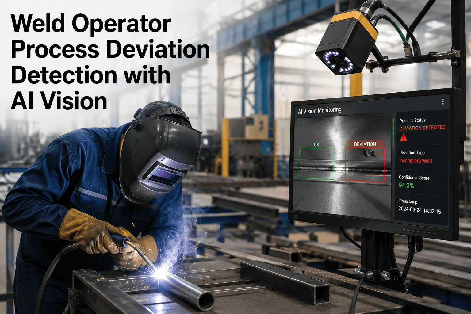
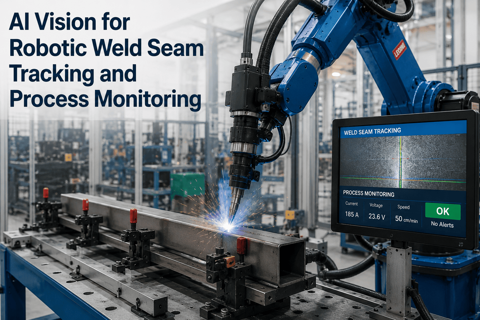
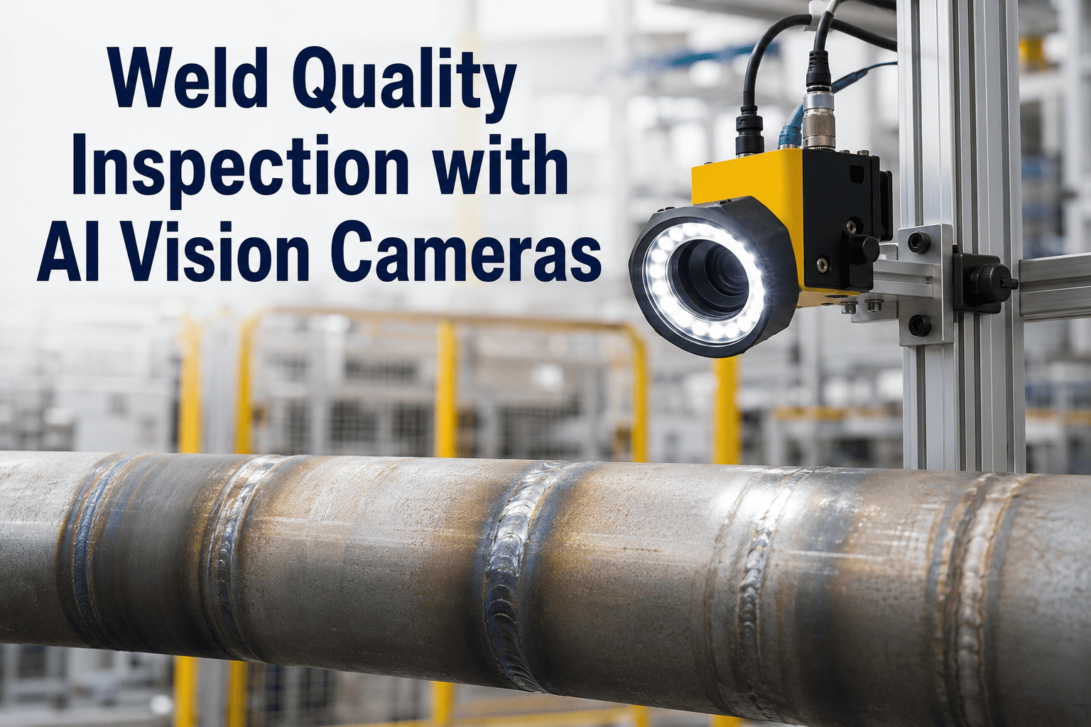
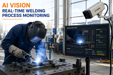
By the time a welded joint fails ultrasonic testing three stations down the line, the arc that created the defect finished burning minutes or hours ago, and whatever caused it is long gone. Welding is one of the only manufacturing processes where the defect and its root cause both disappear the instant the arc goes out, which is why catching problems after the fact costs so much more than catching them while the weld is still forming. The arc, the molten pool, and the spatter pattern all carry visible signals of process stability in real time, and a high-speed camera trained to read them can flag instability before it becomes a defect. See how AI vision weld monitoring reads these signals on a live production line.
PROCESS CONTROL · WELDING
Three Signals, Read Thousands of Times Per Second
Arc brightness, molten pool geometry, and spatter volume all shift in visible, trackable ways well before a weld defect becomes visible from outside the joint.
ARC
Brightness and stability patterns reveal current fluctuation and transfer mode before a defect forms
POOL
Molten pool shape and oscillation frequency correlate directly with penetration depth and fusion quality
SPATTER
Spatter volume and pattern is the visible signature of an unstable metal transfer process
WHY THE OLD APPROACH FALLS SHORT
Post-Weld Inspection Finds the Defect, Never the Cause
Radiographic and ultrasonic testing are good at telling you a weld failed. They are much worse at telling you why, because by the time a part reaches inspection, the process conditions that produced the flaw are gone. A welder or robot cell can drift out of spec for an entire shift before a downstream inspection catches the pattern, and by then dozens of parts may carry the same undetected defect. Experienced welders try to compensate by watching the molten pool directly and adjusting in real time, but prolonged observation causes fatigue, slows reaction time, and exposes the operator to welding fumes the entire time they're staring at the arc. Sampling-based inspection compounds the problem further, since checking one weld in every batch of ten or twenty means a drift that starts between sampled parts can run undetected until the next scheduled check catches up to it.
77%
of welding defects, including excess spatter, trace back to improper process conditions rather than material defects
85%
spatter reduction achievable through better parameter tuning informed by real-time process visibility
21%
operating cost reduction demonstrated from reduced spatter, labor, and consumable use in one documented case
READING THE ARC SIGNAL
A Stable Arc and an Unstable One Look Completely Different
Metal transfer during arc welding happens in one of three modes, and each has a distinct visual signature that a high-speed camera can distinguish in real time. Spray transfer produces a steady, controlled arc with minimal spatter. Short-circuit transfer cycles the arc on and off dozens or hundreds of times per second as the wire bridges and breaks contact with the workpiece. Globular transfer, the least desirable of the three, produces large uneven droplets, wide arc brightness swings, and heavy spatter. Watching which mode is active, and how consistently it holds, tells you far more about weld quality in progress than any post-weld test can reconstruct afterward. A process that starts in a stable spray mode and drifts toward globular transfer partway through a pass is showing exactly the kind of transition a camera can catch mid-weld that a welder glancing at the joint every few seconds is likely to miss entirely.
| Transfer Mode |
Arc Signature |
Typical Outcome |
| Spray Transfer |
Steady brightness, consistent arc length |
Low spatter, stable penetration |
| Short-Circuit Transfer |
Rapid on-off cycling, rhythmic pattern |
Acceptable when frequency stays consistent |
| Globular Transfer |
Large brightness swings, irregular droplet drop |
Heavy spatter, poor fusion risk |
| Erratic or Wandering Arc |
Unpredictable brightness with no repeating pattern |
High risk of undercut, lack of fusion, porosity |
READING THE MOLTEN POOL
Pool Geometry Is the Clearest Predictor of Penetration Quality
The weld pool's width, length, and surface oscillation frequency change measurably before a fusion problem becomes visible from outside the joint. A pool that narrows unexpectedly, oscillates at an irregular frequency, or shifts position along the joint centerline is showing the early visual signs of incomplete penetration or lack of fusion, often several frames before the defect actually forms in the solidified weld. High-speed imaging captures these transient pool behaviors at a resolution no human eye, tired or not, can track consistently across a full shift. Research into vision-based pool monitoring has repeatedly found that abrupt shifts in pool centroid position correlate strongly with fusion defects, which means the camera isn't guessing at a correlation, it's tracking the same physical signal that experienced welders learn to watch for intuitively, just faster and without fatigue.
Pool Width and Length
Directly correlates with heat input and travel speed, key inputs to penetration depth.
Oscillation Frequency
Regular oscillation indicates stable convection, irregular oscillation signals disruption in the pool.
Centroid Drift
Sudden shifts in pool center position along the joint are strongly correlated with lack of fusion events.
Surface Profile
Convex or concave pool surface shape indicates whether the joint is receiving adequate fill.
READING THE SPATTER PATTERN
Spatter Isn't Just Cleanup Work, It's a Warning Sign
Excessive spatter rarely occurs in isolation. It's the visible byproduct of the same instability that produces porosity, undercut, and inconsistent fusion, which is why spatter volume and pattern function as an early indicator worth tracking on their own. A sudden spike in spatter generation partway through a weld pass usually means something in the process, current, voltage, contact tip distance, or shielding gas coverage, just shifted out of the window that was producing a clean weld moments earlier. Beyond the quality signal, spatter itself carries a real cost in cleanup labor, wasted filler material, and consumable wear, so reducing it through better real-time visibility pays back on the cleanup side even before accounting for the defects it was warning about.
01
High-Speed Capture
Cameras capture the arc, pool, and spatter simultaneously at speeds fast enough to resolve individual droplet transfer events.
02
Signature Classification
The model identifies which transfer mode is active and whether pool geometry and spatter volume are within the stable range learned from good welds.
03
Instability Flagging
Deviation from the stable signature is flagged in real time, often before the resulting defect is visible on the finished bead.
04
Operator or Controller Alert
Manual cells alert the welder immediately, robotic cells can route the flag to the weld controller for parameter correction.
05
Weld-Level Traceability
Every weld is logged with its stability profile, giving quality teams a per-joint record instead of a sampled inspection snapshot.
WHAT INSTABILITY ACTUALLY PRODUCES
Connecting the Signal to the Defect It Predicts
Process instability doesn't produce random outcomes, it produces the same predictable defect categories over and over depending on which signal shifted. Knowing the connection between the signal and the likely defect turns a flagged instability event into an actionable correction instead of just a warning light. Industry analysis has found that the large majority of welding defects, spatter included, trace back to improper process conditions rather than material flaws, which means the signal a camera is watching is very often the same root cause a defect investigation would eventually land on anyway, just discovered while the weld is still forming instead of after it's already failed inspection.
Porosity
Gas voids trapped in the solidifying pool, often preceded by irregular pool oscillation and inconsistent shielding gas coverage visible in the arc signal.
Lack of Fusion
Insufficient bonding between weld and base metal, commonly preceded by centroid drift in the pool or a narrowing pool width along the joint.
Undercut
A groove melted into the base metal at the toe of the weld, associated with excessive current or travel speed visible as arc brightness spikes.
Excessive Spatter
A direct visible signal of unstable metal transfer, frequently the first sign of a broader process drift before other defects appear.
Start a Pilot on Your Highest-Volume Weld Cell
Validate signal-to-defect correlation against your own joints and process parameters before expanding to additional cells.
TURNKEY DEPLOYMENT, READY TO INSTALL
Hardware and Software Ship Together, Pre-Configured
iFactory ships a pre-configured NVIDIA AI server, racked and ready, with weld monitoring software pre-loaded. Rack it, plug power and Ethernet, and the system is capturing arc, pool, and spatter data on your line. Cameras and mounting hardware are sized to your weld cell geometry and joint access before the equipment ever leaves the shop, so installation is a matter of positioning pre-configured hardware rather than engineering a camera mount from scratch on the shop floor.
Pre-configured NVIDIA edge AI hardware, racked and shipped ready to install
High-speed cameras and mounting hardware sized to your weld cell and joint geometry
Model training on your specific process, material, and joint types included, not billed separately
Cabling, network integration, and weld controller connection for robotic cells
Operator training and documentation for the go-live team
Twenty-four seven remote monitoring from day one of production
FROM CONTRACT TO PRODUCTION
Live in 6 to 12 Weeks
Weeks 1–4
Ship, Install, and Baseline Capture
Hardware ships pre-racked. Cameras mounted at each weld cell, and baseline signal data collected across your current known-good welds.
Weeks 5–8
Model Training and Pilot Run
The model is trained on your specific arc, pool, and spatter signatures, then validated against live production before it's given alert authority.
Weeks 9–12
Go-Live and Operator Training
System takes live alert authority with operator training complete and remote monitoring active around the clock from the first production shift.
WHAT CHANGES ON THE FLOOR
From Reactive Rework to Correction Mid-Pass
The practical difference between a facility with process monitoring and one without shows up long before anyone calculates a return on investment. Without it, a shift ends, parts move to inspection, and a batch comes back flagged for rework, at which point nobody can say with certainty which pass, which minute, or which parameter drift actually caused it. With continuous arc, pool, and spatter monitoring, the same drift gets flagged the moment it starts, whether that means an automated correction on a robotic cell or an alert to the welder on a manual one. The rework that used to happen after the fact, grinding out a bad pass and re-welding it with a second heat cycle that can itself introduce new metallurgical risk on sensitive alloys, increasingly just doesn't happen, because the process never drifted far enough to produce the defect in the first place.
Before Monitoring
Defects discovered downstream, root cause reconstructed after the fact, rework introduces a second heat cycle.
After Monitoring
Instability flagged mid-pass, correction applied in real time, defect rate drops before it ever reaches inspection.
FREQUENTLY ASKED QUESTIONS
What Weld Engineers Ask Before Adopting Process Monitoring
Does this replace post-weld NDT like radiographic or ultrasonic testing?
No, and it isn't trying to. Real-time process monitoring catches process instability while the arc is running, which is a different layer of quality control than NDT methods that verify the final weld's internal integrity after the fact. The two are complementary rather than competing, since catching instability in process reduces how often NDT finds a defect in the first place, while NDT remains the method of record for verifying joints in critical or code-governed applications. Facilities running both typically see NDT reject rates drop meaningfully once process monitoring is catching drift before it produces a defect.
Book a demo to see how the two fit together on your line.
Can this work on manual welding cells, or is it only for robotic automation?
It works on both, though the response differs. On a robotic cell, a flagged instability event can route directly to the weld controller for an automated parameter correction mid-pass. On a manual cell, the same detection triggers an alert to the welder, giving them the same kind of real-time feedback an experienced eye watching the pool would provide, without the fatigue and fume exposure that comes from staring directly at the arc for an entire shift. Many facilities start with manual cells specifically because that's where operator fatigue creates the most inconsistency shift to shift.
Contact support to scope monitoring for your specific cell types.
How does the system tell the difference between an acceptable short-circuit cycling pattern and an actual problem?
Short-circuit transfer is a normal, expected part of many welding processes, and the model is trained specifically to recognize your process's stable cycling frequency and brightness pattern as the baseline rather than treating all cycling as suspect. What actually gets flagged is a deviation from that learned baseline, an irregular frequency, an unusual brightness swing, or a pattern that breaks from the rhythmic cycling a healthy short-circuit transfer normally shows. This is why baseline capture during onboarding matters so much, since the system needs real examples of your specific good welds before it can reliably tell a normal pattern from a developing problem.
What happens when we change materials, joint design, or weld process entirely?
A significant change to material, joint geometry, or welding process shifts what a normal arc, pool, and spatter signature looks like, so it typically requires a retraining pass using sample welds from the new configuration before the system resumes full alert authority on that specific setup. This is standard ongoing model maintenance rather than a full redeployment, and facilities running frequent product changeovers or multiple weld processes on the same line should expect this retraining cadence to happen more often than a single-process, single-material operation. Planning for this upfront avoids a detection gap right when a new process configuration goes into production.
Is this worth the investment for a lower-volume fabrication shop rather than a high-volume automotive line?
Volume affects payback speed but doesn't determine whether the underlying value case makes sense, since even a lower-volume job shop welding structural steel or pressure vessel components deals with the same cost consequences from an undetected lack-of-fusion defect discovered downstream or, worse, in service after the part is already installed. Smaller shops often get the most value starting with a single high-consequence weld cell, structural, pressure-bearing, or code-governed joints, rather than attempting plant-wide coverage immediately, which keeps the initial investment proportional to risk while still generating the process data needed to justify wider deployment later across additional cells and product lines.
Stop Discovering Weld Defects After the Arc Goes Out
iFactory ships turnkey AI vision hardware and software to read arc, pool, and spatter signals in real time, catching instability before it becomes a defect.