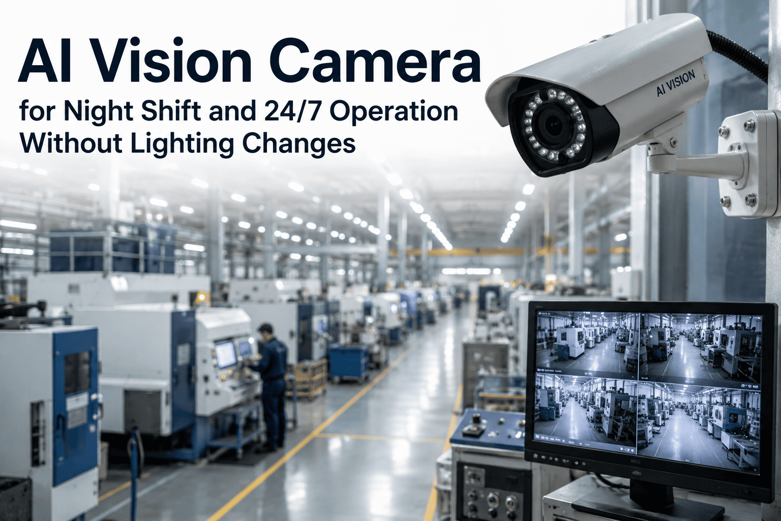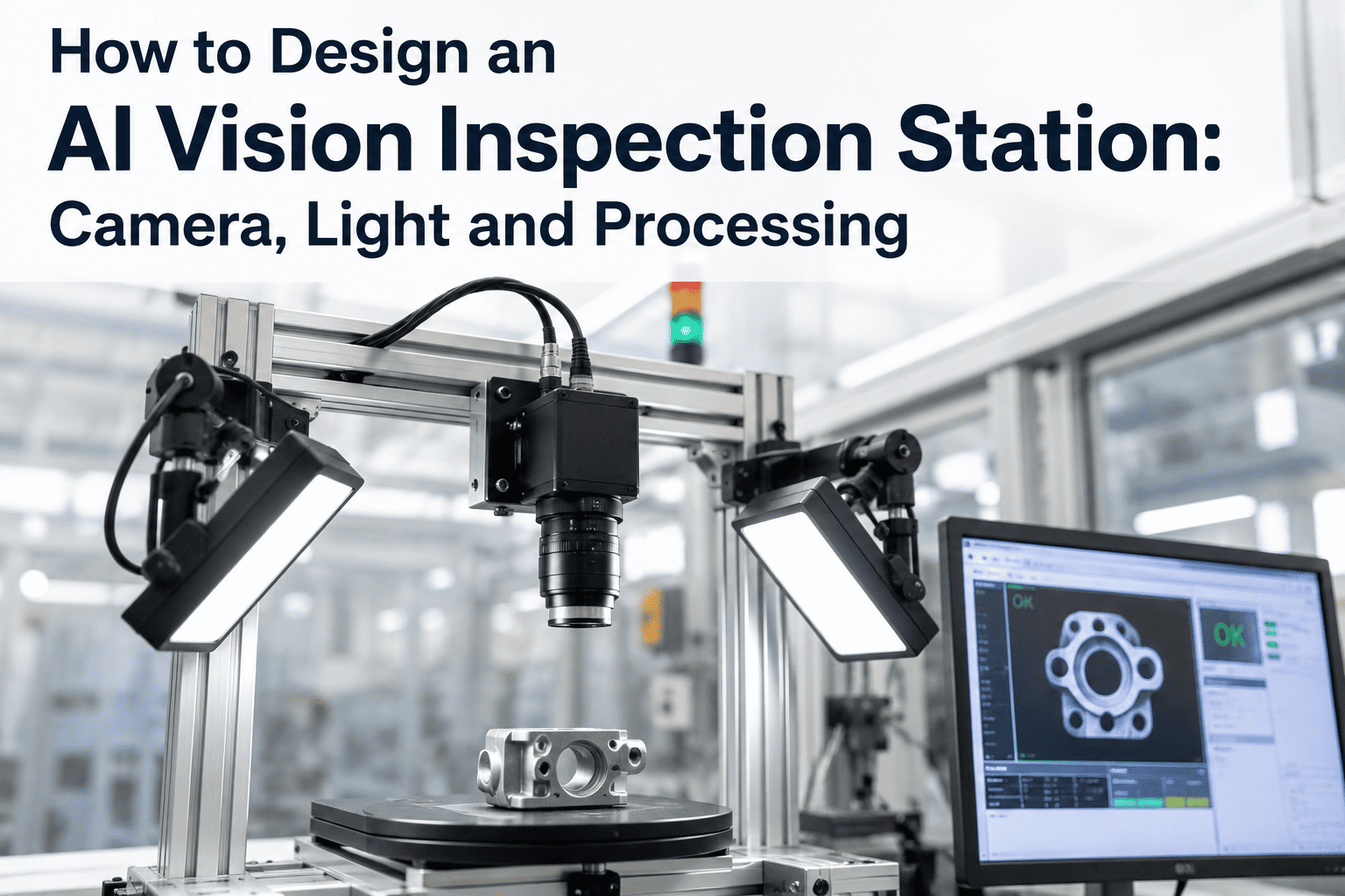
A vision inspection station is where cameras, optics, illumination, and compute converge into a single decisive judgment: pass or fail, in milliseconds, on every unit. The difference between a station that catches 99.6% of defects and one that ships escapes to customers is almost never the AI model. It is the physics of the capture — the lens, the light angle, the exposure trigger, and the processor that has to keep up with line speed. This guide walks through every design choice, in the order a systems engineer actually makes them, so your station is built once and built right. If your team is scoping a new inspection cell, book a design consult with iFactory before hardware is ordered.
Design the Station Once. Inspect Every Unit for the Next Decade.
Camera, lens, light, trigger, and edge processor selected against defect physics — not catalog defaults. Built to survive vibration, dust, coolant mist, and the third shift.
Why the Station, Not the Algorithm, Decides Inspection Outcomes
A well-tuned deep-learning model on a poorly designed station will underperform a mediocre model on a well-designed one. The reason is simple: the AI can only classify what the camera actually captured, and what the camera captured depends entirely on how light strikes the part, how the optics resolve the defect, and how cleanly the trigger freezes motion.
The Six Building Blocks of a Vision Inspection Station
Every station, whether inspecting semiconductor wafers or beverage bottles, is built from the same six subsystems. The specifications differ. The order of design decisions does not. Skip one and the rest cannot compensate.
Camera
The sensor that converts photons to pixels. Choice governed by resolution needed for smallest defect, plus line speed.
Lens
Focal length, aperture, and mount that project the scene onto the sensor. Chosen after field of view and working distance are fixed.
Illumination
Geometry and spectrum of the light source. Determines what the defect looks like to the sensor before AI ever sees the frame.
Trigger
Signal that tells the camera exactly when to expose. Hardware-triggered on a sensor edge, never software polling, for repeatability.
Edge Processor
Local compute that runs the AI inference and returns pass or fail in time for the downstream reject actuator to act.
Enclosure
The physical housing sealing everything against vibration, ambient light, dust, coolant, and shift-to-shift disturbance.
Camera Selection: Match the Sensor to the Defect
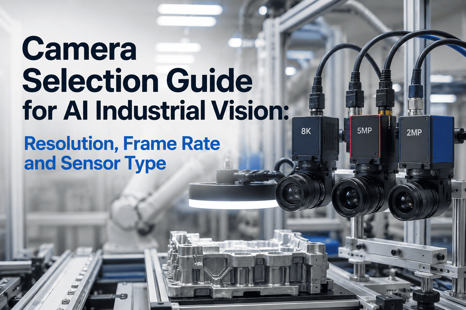
Camera choice is driven by three questions in order: what is the smallest defect you must detect, how fast is the part moving, and does the defect show up in visible light at all. The answer collapses the shortlist to a single family.
The default for 80% of stations. Captures a full 2D frame per trigger. Resolutions from 2 MP for cap inspection to 45 MP for PCB assembly. Global shutter mandatory when parts are still in motion.
Captures one row at a time synchronized to encoder pulses. Ideal for print webs, textile rolls, extrusions, and bottle wraps. Removes the need to fit an entire part into one frame.
Captures dozens to hundreds of wavelengths per pixel. Distinguishes materials that look identical to RGB cameras — plastic types, food contaminants, moisture content — by their spectral signature.
Reveals features invisible to visible sensors: heat-seal completeness on pouches, water content in produce, delamination inside composites. Short-wave infrared sees through many polymers.
Lens Math: From Field of View to Focal Length
The lens is the only component chosen by calculation, not by opinion. Once field of view, working distance, and sensor size are known, focal length falls out of a single equation. Get this wrong and no amount of AI training rescues it.
Width of the scene you need to capture, plus 10–15% margin for part-position variation. A 100 mm wide can requires a 115 mm FoV.
Distance from lens front to part surface. Set by the mechanical envelope: guarding, reject arms, safety curtains, and cleaning access.
Physical width of the camera sensor in millimeters. Read from datasheet — not the pixel count. A 2/3 inch sensor is 8.8 mm wide.
f = (WD × sensor width) ÷ FoV. Round to nearest catalog value — 8, 12, 16, 25, 35, 50 mm. If none fits, revisit WD.
Smallest defect must span at least 3 pixels for reliable AI detection. Divide FoV by camera pixel width to check: a 100 mm FoV on 2448-pixel sensor gives 41 μm per pixel — a 0.15 mm defect covers 3.6 pixels. Good.
Aperture drives depth of field. On stations where parts vary in height, close the aperture (higher f-number) to keep the full part in focus — then compensate with brighter illumination or longer exposure.
If defect judgment depends on measured dimensions — bore diameter, thread pitch, cap seat depth — use a telecentric lens. It removes perspective distortion so a part at 5 mm height reads the same as at 8 mm height.
Lighting Geometry: What the Light Reveals or Hides
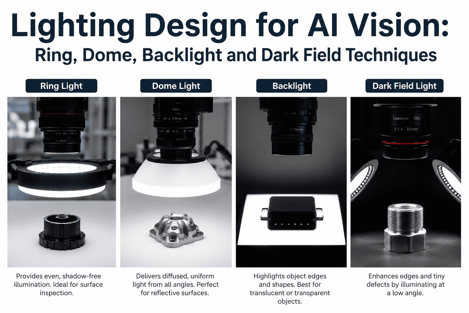
Illumination is the single highest-leverage variable in station design. The same camera, the same lens, the same AI model can find a defect that was invisible ten minutes earlier — all by changing the angle and pattern of the light. Here is the working playbook for choosing among five canonical geometries.
Best for: printed labels, barcode read, flat matte surfaces
Poor for: specular metals — creates hotspots that saturate the sensor
Best for: surface scratches, embossed serials, edge chips on lenses
Poor for: broad surface uniformity checks — flat areas appear dark
Best for: shiny curved parts, cosmetic jars, chrome components
Poor for: catching fine scratches — diffusion hides low-relief defects
Best for: dimensional checks, presence-absence, edge measurements
Poor for: any surface feature — you see outline only, no texture
Best for: flat reflective surfaces, silicon wafers, mirror parts
Poor for: 3D or textured parts — angle-sensitive, tight geometry
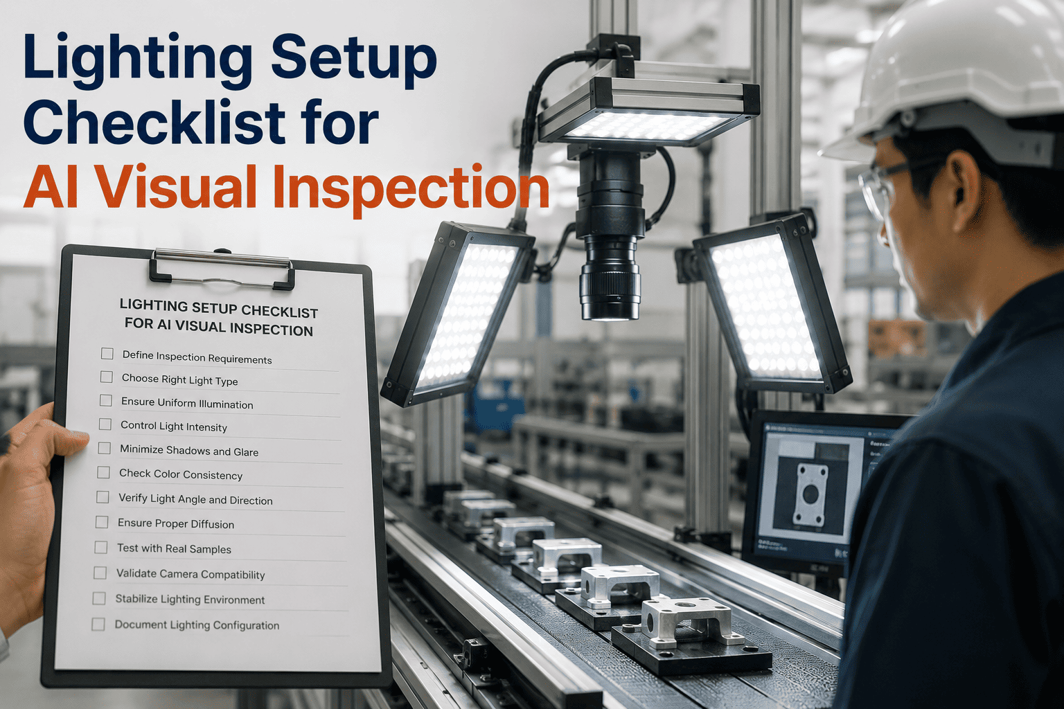
Prototype with a lighting kit before ordering hardware. Two hours of A/B testing on the actual defect samples saves months of AI retraining downstream. When in doubt, favor diffuse over direct for cosmetic parts and dark field for surface flaws.
Get the Station Right Before the Order Goes In
iFactory's vision engineers scope camera, lens, lighting, and processor against your specific defect samples — before you commit to hardware. One 30-minute call converts a shopping list into a validated bill of materials.
Trigger Mechanism: The Millisecond That Determines Repeatability
The trigger tells the camera the exact moment to expose. On a moving line, a variable trigger produces variable framing, variable framing produces variable AI inference, and variable inference produces defect escapes. Trigger design is a discipline of eliminating jitter.
A photoelectric sensor, encoder pulse, or PLC digital output fires directly into the camera trigger pin. Latency is deterministic in microseconds. Every part is captured at the exact same position, exposure after exposure, shift after shift.
- Latency: 1–10 μs, jitter under 1 μs
- Repeatability: better than 0.05 mm at 2 m/s line speed
- Wiring: single opto-isolated 24 V line to camera I/O
- Recommended for every production station without exception
Application code sends a trigger command over Ethernet or USB. Latency varies with OS scheduling, network load, and USB bus contention. Fine for offline algorithm development, unfit for production capture.
- Latency: 5–50 ms, jitter 1–20 ms
- Repeatability: 2–40 mm at 2 m/s line speed
- Wiring: none, but bandwidth-shared with image transfer
- Acceptable only in stop-motion or non-critical stations
Edge Processor Selection: Match Compute to Model and Line Speed
The processor sits between the camera and the reject actuator. Its job is to run AI inference on every frame and return a verdict inside the cycle time budget. Undersize it and units ship uninspected; oversize it and you overspend on every station.
Rule of thumb: cycle time budget equals 1 divided by line rate, minus 20 ms buffer for reject actuation. A 300 unit-per-minute line has 200 ms per unit; inference must finish inside 180 ms. Anything tighter demands the next tier up.
Physical Enclosure: The Housing That Protects the Physics
The enclosure is where every design decision either survives or fails. Ambient light gets in and washes out contrast. Vibration walks the camera out of focus. Coolant mist coats the lens. A vision station without a properly specified enclosure has a shelf life measured in months.
- Full light-tight tunnel around camera, part, and illumination path
- Matte-black interior surfaces to prevent secondary reflections
- Entry and exit slots sized to part envelope plus 20 mm clearance
- Baffles at each opening to block off-axis ambient light
- IP54 minimum for dry environments, IP65 for washdown zones
- Positive-pressure air purge for dusty or coolant-heavy areas
- Anti-vibration mounts under camera and lens assembly
- Thermal budget calculated for LED heat plus processor draw
- Front-access door for lens cleaning without conveyor stop
- Cable strain relief and labeled connectors on external junction
- Golden-sample slot for daily verification without part flow
- Status indicator visible to line operator from working position
The Eight-Step Station Design Workflow
This is the sequence experienced vision engineers follow, and the sequence iFactory uses on every scoping engagement. Each step feeds the next; skipping ahead almost always means backtracking.
Photograph 20+ defect samples. Document size in mm, contrast against background, and how it appears versus good parts.
Measure line speed, part spacing, mechanical envelope, safety clearances, and cycle time budget.
Test five geometries against actual samples using a lighting kit. Choose the one giving highest defect contrast.
Compute pixels needed for smallest defect at 3-pixel coverage. Select sensor resolution and shutter type.
Apply focal length formula. Choose nearest catalog value. Verify depth of field covers part height variation.
Specify hardware trigger source, opto-isolation, and cable routing. Test jitter with encoder pulses before go-live.
Match processor tier to inference budget. Benchmark chosen model on target hardware with real captured frames.
Design light-tight tunnel, sealed to environment rating, with service access and golden-sample verification slot.
Five Design Mistakes That Sink Vision Projects
Every experienced integrator has seen these failure patterns. They cost weeks of rework and often the credibility of the whole vision initiative. Catch them in design review.
Buying the camera first
The camera is chosen after the defect, the lighting, and the field of view — not before. Teams that start from a catalog camera invariably discover the resolution is wrong or the sensor is too small for the lens they now need.
Ignoring ambient light
Overhead fluorescents, sunlight through skylights, and stack-light strobes all bleed into unsealed stations. Contrast crashes at 3 PM when the sun angle shifts. The fix is a proper tunnel, not a bigger AI model.
Skipping the lens calculation
Using whatever focal length is on hand yields wrong field of view, wrong pixel-per-mm ratio, and defects that occupy fewer than 3 pixels. No amount of AI retraining recovers detail the optics never captured.
Software triggering in production
Software triggers introduce millisecond-scale jitter. Parts are captured at slightly different positions each cycle, and the AI sees a moving reference. Hardware trigger is not a nice-to-have — it is baseline.
Undersizing the processor
A model that ran fine on a workstation drops to a fraction of the frame rate on an edge processor. Benchmark on the target hardware, on the target model, at target resolution, before the line depends on it.
Frequently Asked Questions
How long does it take to design and commission a new vision inspection station?
A well-scoped station moves from kickoff to live inspection in eight to twelve weeks. The first two weeks go to defect characterization and lighting prototyping against real samples. Weeks three to six cover hardware procurement and enclosure build. Weeks seven to ten cover AI model training on captured data, and the final phase is parallel-run validation against manual inspection. Rushing the defect characterization phase is the single most reliable way to add months to the schedule, so book a scoping call before hardware is ordered.
Can we retrofit an existing conveyor, or does the station need a dedicated line section?
Most stations retrofit onto existing conveyors with modest modifications. Requirements are a stable, flat section where parts pass in a repeatable orientation, a mounting frame for the enclosure that isolates it from conveyor vibration, an entry point for the trigger sensor, and access to compressed air for the reject actuator downstream. The design consult includes a site survey to verify these conditions and identify any structural changes needed before enclosure fabrication.
What ambient conditions will the station tolerate, and do we need special environmental packaging?
Standard industrial enclosures are rated IP54 and comfortable in dry factory environments between 5 and 40 degrees Celsius. Washdown zones in food and beverage require IP65 stainless housings with sealed cable glands and gasketed access doors. Environments with heavy coolant mist, metal chips, or fine dust benefit from positive-pressure air purge that keeps the optical path clean and extends service intervals from weekly to quarterly. Our support team helps specify the right environmental package for your zone.
How does the station connect to our existing MES, ERP, or SCADA systems for traceability?
The edge processor exposes results through the industrial protocol your plant already speaks: OPC UA, MQTT, Modbus TCP, EtherNet/IP, or a REST API for higher-level systems. Every capture is stamped with batch number, line, timestamp, verdict, defect class, and confidence score, then streamed to your historian or MES for full unit traceability. The iFactory platform also stores the image itself for audit review, so a customer complaint six months later can be reconciled against the exact frame the station captured.
What happens when a new product variant is introduced — does the AI model need full retraining?
A well-designed station handles product changeovers as a recipe swap, not a rebuild. The camera, lens, lighting geometry, and enclosure stay identical; what changes is the region-of-interest mask, tolerance settings, and reference model for the new SKU. New product families with different geometry or color may need incremental training, typically completed in one to two weeks using transfer learning on a few hundred labeled samples, which is far faster than the original model build.
Design With Physics First, Deploy With Confidence
A vision inspection station is a physics instrument that happens to have AI attached. Every high-performing installation traces back to disciplined choices made in the first two weeks of design: the right defect samples, the right lighting geometry, the right pixel budget, the right trigger source. Get those right and the rest of the project is engineering. Get them wrong and no downstream fix compensates. This is why iFactory's vision engineers scope the physics before the parts list, and why the pilot stations we commission run for years without model degradation or hardware surprises.
Ready to Design Your Next Vision Station?
Book a 30-minute design consult with an iFactory vision engineer. Bring a defect sample or a candidate part; leave with a validated camera, lens, lighting, and processor specification plus a pilot proposal with a fixed price and ten-week timeline.