Lighting Design for AI Vision: Ring, Dome, Backlight and Dark Field Techniques
By Johnson on July 21, 2026
When AI vision systems miss defects or throw false positives, the camera and algorithm usually get the blame. The real culprit almost always hides in plain sight — the lighting. Industry benchmarks show that proper illumination determines up to 70 percent of inspection success, more than camera resolution, lens quality and algorithm sophistication combined. The right technique — ring, dome, backlight or dark field — makes invisible defects obvious to any model, while the wrong one turns even the best neural network into an expensive random number generator. To see how iFactory engineers pair the correct lighting geometry with vision AI on live production lines, book a working demo with our team.
Machine Vision Lighting Playbook
Ring, Dome, Backlight or Dark Field? The Lighting Choice That Controls 70% of Your Inspection Accuracy
Every defect has a lighting signature. Match the technique to the flaw and the AI works. Get it wrong and no algorithm can rescue the image.
70%
Of vision accuracy comes from lighting, not cameras
4
Core techniques cover ~95% of factory inspections
10x
Contrast gain from switching to the right wavelength
Why Lighting Beats Cameras, Lenses and Algorithms Combined
Most plants pour budget into higher-megapixel cameras and larger AI models when accuracy plateaus. The bottleneck is almost never resolution — it is contrast. A model can only classify what the sensor recorded, and lighting decides whether a scratch, a bubble or a missing pin enters the image as a visible signal. A 20-megapixel sensor on a shiny bearing under fluorescents produces hotspots. The same bearing under a dome light lets a 2-megapixel camera catch a hairline crack. Illumination is the first design decision in every serious vision project.
Where Vision Accuracy Actually Comes From
Lighting geometry & wavelength
70%
Optics (lens, working distance, aperture)
15%
Camera sensor & resolution
10%
AI model architecture & training
5%
Approximate industry estimates. No algorithm can recover information that lighting never captured.
The Four Core Techniques at a Glance
Dozens of specialist geometries exist, but four cover almost every factory inspection ever built. Each solves a different physics problem: direct light for matte parts, diffuse for shiny curves, transmitted for edges, grazing for surface texture.
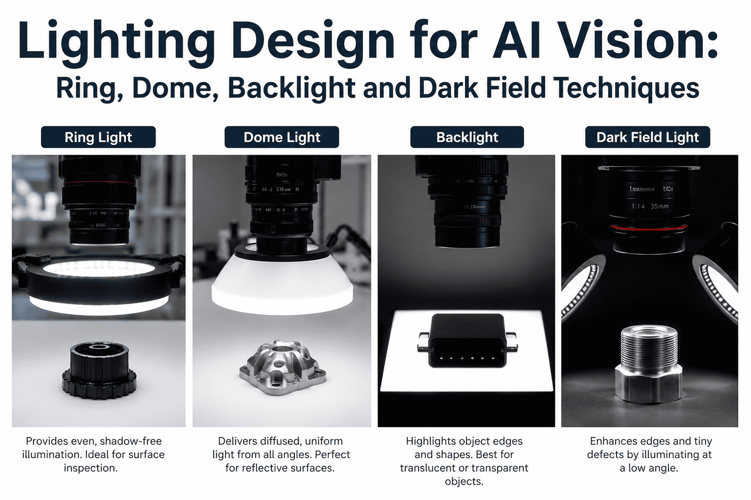
Ring Light
Direct / bright field
LEDs arranged around the lens, aimed at the object. Workhorse for flat matte parts, print, presence checks and OCR on non-reflective surfaces.
Dome Light
Diffuse / shadowless
Hemispherical diffuser with LEDs on the rim. Light bounces off the interior to wrap the object in shadow-free illumination — the answer for shiny, curved specular surfaces.
Backlight
Transmitted / silhouette
Light behind the object, camera in front. Produces a hard silhouette on a bright field — the most robust setup for gauging, hole detection and edge measurement.
Dark Field
Grazing / low angle
Light striking the surface at 45° or lower. Smooth areas stay dark; scratches, engravings and bumps scatter light and appear bright.
Ring Light: The Direct Illumination Standard
The ring light is the default on 60 to 70 percent of factory installations because it just works on flat, matte, non-reflective parts. LEDs around the lens throw light onto the object, and the reflection reaches the sensor with strong brightness and solid edge contrast.
How it works
A circular LED array concentric to the lens throws light onto the part. Because light returns along the camera axis, matte surfaces reflect evenly and the image looks bright and balanced.
Best for
Flat matte parts, PCBs
Print & label OCR
Presence checks
Bar & QR reading
Struggles with
Shiny metal & glass — hotspots
Curved specular parts
Fine surface scratches
Sub-pixel edges
Dome Light: Diffuse, Shadowless, Reflection-Proof
The moment a shiny bottle or specular metal enters the cell, a ring light fails. Hotspots wash out image regions and the AI cannot learn features that shift with every rotation. The dome light — often called the salad bowl — solves this with pure diffuse illumination.
How it works
LEDs sit on the rim of a hemispherical diffuser, pointing up. Light bounces off the inner dome surface and reaches the part from every angle at once — shadow-free, glare-free illumination.
Best for
Shiny specular metal
Bottles, cans, jars
Codes through cellophane
Embossed labels & print
Struggles with
Fine scratches (too diffuse)
Very short working distance
Tight mount clearance
Sub-pixel edge accuracy
Backlight: When the Silhouette Is the Answer
Backlighting is the mathematically cleanest technique in machine vision. A diffuse source behind the object gives the camera a pure black silhouette on a bright field — no surface finish dependency, no colour interference, no glare. Every serious dimensional gauging system uses it.
How it works
A flat diffuse panel sits behind the part with the camera facing it. Opaque objects block the light and appear as sharp black silhouettes — often to sub-pixel edge accuracy with monochrome red or blue LEDs.
Best for
Dimensional gauging
Hole & gap detection
Presence & orientation
Transparent object edges
Struggles with
Any surface defect
Colour & print reading
Stacked/occluded parts
Internal features
Dark Field: The Surface Defect Hunter
Dark field is the least understood but often most powerful of the four techniques. LEDs strike the surface at 15 to 30 degrees. Smooth areas reflect light away and appear near-black. Anything that disturbs the surface — scratch, engraved code, dust, raised burr — scatters light back into the lens and pops as a bright feature on a dark background.
How it works
Low-angle LEDs graze the surface. Flat regions reflect light away from the sensor and appear dark. Micro-features — scratches, engravings, contamination — scatter light back and pop as bright signals on a black background.
Best for
Scratches on polished metal
Engraved marking OCR
Contamination detection
Weld & texture checks
Struggles with
Overall shape/gauging
Flat matte print
Colour classification
Very tall parts
Not Sure Which Lighting Setup Your Line Needs?
iFactory vision engineers run free lighting audits — sending sample images taken under ring, dome, backlight and dark field with your part on our test bench. See which technique makes your defects visible before buying a single LED.
Match Defect to Technique: The Vision Lighting Matrix
Once you understand what each technique does, choosing becomes a lookup exercise. Below is the matrix experienced integrators use to shortlist geometries before hardware ships.
Inspection Task
Ring
Dome
Backlight
Dark Field
Edge & hole dimensional measurement
Fair
Poor
Best
Poor
Print/label OCR on paper or plastic
Best
Fair
Poor
Poor
OCR on engraved or laser-marked metal
Poor
Fair
Poor
Best
Scratches on polished surfaces
Poor
Fair
Poor
Best
Codes through cellophane wrap
Poor
Best
Poor
Poor
Curved specular parts (bottles, cans)
Poor
Best
Fair
Poor
Presence/absence of small components
Best
Fair
Best
Fair
Hairline crack in polished bearing
Poor
Poor
Poor
Best
Wavelength Strategy: The Second Half of Lighting Design
Geometry decides where light comes from. Wavelength decides what it reveals. The same dome light with a red LED versus a blue LED can produce two completely different images — one where a defect vanishes, one where it screams. Wrong colour is the single most common reason a correct geometry still fails.
UV
365 – 405 nm
Excites fluorescence in adhesives, inks and biological residues. Reveals security marks, verifies UV-cure coating coverage, exposes invisible contamination.
Blue
450 – 495 nm
Shortest visible wavelength scatters more, giving sharper edges on tiny features. Preferred for micro-electronics and small-component alignment.
White
Broadband
Only choice when true colour classification matters — food grading, colour-coded assembly, packaging verification. Needs stable colour temperature.
Red
620 – 660 nm
Long wavelength transmits well through translucent films and darkens complementary green features. Great for reading print through wrappers.
NIR
780 – 940 nm
Penetrates thin coatings, neutralises colour and rejects ambient light. Used for wafer inspection, sub-surface bruise detection in fruit and coating checks.
SWIR
1050 – 1650 nm
Sees through opaque plastics and measures moisture, fill level and material composition. Reads through IR-transparent bottle walls.
Five Lighting Mistakes That Kill Vision AI Projects
Every vision integrator has seen these mistakes wreck otherwise well-specified inspection cells — the reason projects that looked perfect in the lab collapse in production.
01
Relying on ambient factory light
Fluorescents flicker at 100-120 Hz, sunlight shifts hourly, and forklift lamps sweep past constantly. Any inspection depending on ambient light will drift with the sun and fail the first cloudy afternoon.
02
Fighting shiny parts with a ring light
Ring lights on specular metal or glass produce donut hotspots that shift with every rotation. The AI learns the hotspot instead of the defect, and accuracy collapses when orientation changes.
03
Ignoring wavelength when parts have colour
White light washes out traces on a green PCB. Red light makes the green solder mask appear near-black and reveals every trace and pad in high contrast. Colour choice is a design decision, not a preference.
04
Uneven illumination across the field of view
A brighter centre than edges — common with cheap ring lights — means the AI sees the same defect differently depending on its position in the frame. Uniformity across the full field of view is non-negotiable.
05
Skipping polarisers on reflective materials
Crossed polarisers on light and lens eliminate specular glare from plastics, films and painted surfaces at near-zero cost. Projects that skip this on wet or coated products often blame the algorithm for glare a polariser would have removed.
Frequently Asked Questions
Do I really need dedicated lighting if my camera has auto-exposure?
Auto-exposure adjusts brightness after capture, but it cannot create contrast that was never there. If your defects reflect the same light as the surrounding surface, the sensor never records them regardless of exposure settings. Dedicated lighting produces the specific reflection or scattering signature that separates a defect from a good region — that separation is what exposure amplifies. Skipping dedicated lighting is the single most common cause of failed vision projects. You can book a demo to see the difference on real production images.
How do I choose between dome and dark field for a shiny metal part?
Dome and dark field solve opposite problems on the same shiny surface. Use a dome when you need to see the whole part clearly — shape, markings, geometry — because diffuse illumination kills the glare a ring light creates. Switch to dark field when you need to find scratches, cracks, indentations or engraved codes, because grazing light makes those features pop on a dark background. Many production lines run both together with strobed illumination to capture two images per part. Our engineers can help you decide via our support team.
Can AI compensate for poor lighting with a bigger model?
No — and this is one of the most expensive misconceptions in industrial AI. A neural network can only classify features the sensor actually recorded. If lighting failed to create contrast between a defect and its background, no amount of model depth or training data will recover that lost information. Worse, larger models trained on badly lit images overfit to hotspots and shadows, then fail the moment lighting shifts slightly on the floor. The rule holds across every serious vision team: fix the light first, then choose the model.
What is the typical cost of proper machine vision lighting?
Industrial LED lighting for a single station ranges from a few hundred dollars for a basic ring light to a few thousand for a large dome or specialised dark field ring. Against the camera, lens, controller and AI development cost, lighting is usually the smallest budget line item and delivers the highest return on accuracy. Cutting the lighting budget is the fastest way to inflate every other cost — a poorly lit cell needs more cameras, higher resolution and more retraining cycles. To scope your application, book a free consultation with our vision team.
How does iFactory approach lighting for AI vision deployments?
iFactory treats lighting as the first design decision — not an afterthought. Every deployment begins with a sample-part audit where we photograph your specific defects under ring, dome, backlight and dark field with multiple wavelengths, then send the actual images so you can see which combination reveals the flaw most clearly. Only after lighting is locked do we specify the camera, lens and AI model. This sequence typically cuts model training time by 40 to 60 percent and materially improves accuracy on the floor.
Stop Blaming the AI. Start Fixing the Light.
The gap between a vision project that ships and one that stalls is almost always lighting. iFactory engineers photograph your defects under all four techniques on our test bench, share the actual images, and recommend the exact geometry and wavelength that makes your inspection work — before you commit to hardware.