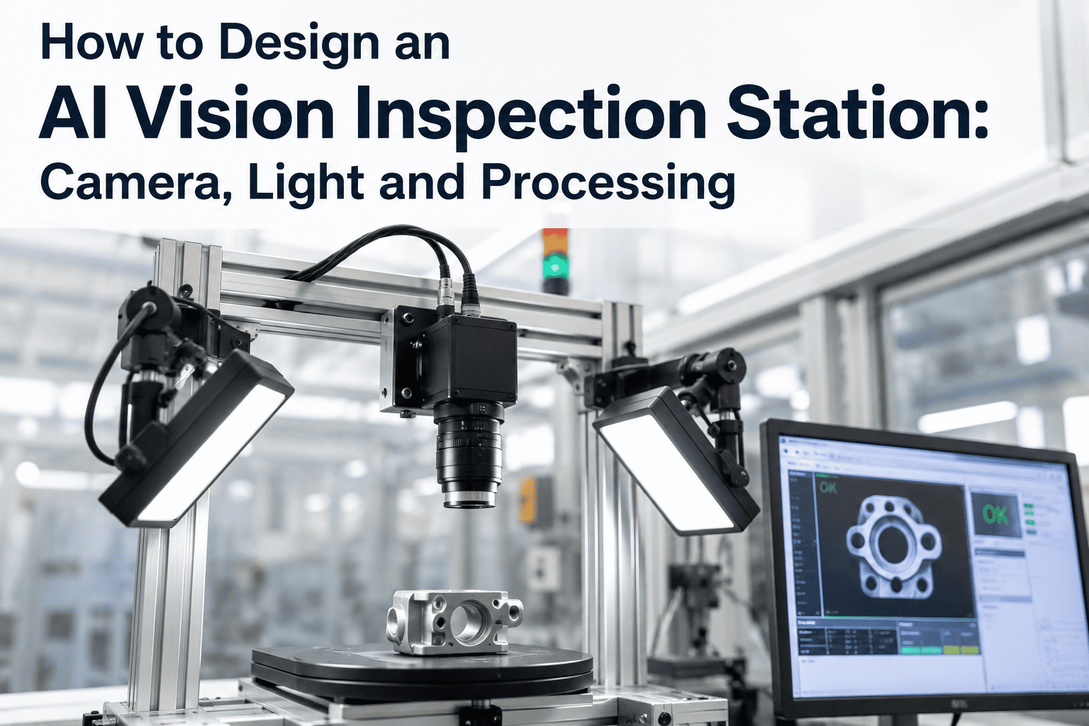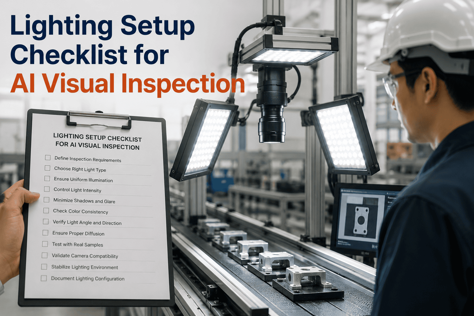
Lighting is the single largest lever in an AI visual inspection system — the right source improves contrast more than any model change and cuts training data needs by half. Bad lighting produces images no neural network can rescue, and the failure looks like a model problem when it is physics. This checklist covers 66 action items across eight phases — pre-setup, technique, positioning, intensity, wavelength, ambient control, controller, and sign-off. Walk it before power-on — book a walkthrough for an engineer to review the completed form.
Lighting Setup Checklist for AI Visual Inspection
A step-by-step verification checklist for machine-vision lighting design. Type, angle, intensity, uniformity, color temperature, ambient control, and controller integration — every illumination decision that anchors AI inspection accuracy on the production line.
How to Use This Checklist
Print or Assign
Print for the vision integrator or assign as a CMMS task against the inspection station ID.
Walk Each Phase in Order
Technique selection feeds positioning, which feeds intensity. Skipping ahead forces expensive rework.
Prove With a Test Image
Every phase produces a saved captured image, a lux reading, or a signed line item.
Sign, File, Handover
Installer and line supervisor sign at completion. Only then does model training begin.
Pre-Setup Planning & Requirements
10 itemsSurface, dimensional, color, presence, texture, or 3D profile — each drives a different lighting choice.
Reflective, matte, translucent, or textured — noted with sample photos before any light is selected.
Phase 03 of the camera placement checklist complete. Lighting geometry is derived from camera geometry.
Max exposure time calculated from line speed and pixel-per-mm target. Drives strobe or continuous decision.
Every shift, sunrise, sunset, and machinery cycle mapped for its impact on the inspection zone before ordering hardware.
Food-safe housing, IP rating, ATEX certification, or eye-safety class documented per site regulation.
24VDC, 48VDC, or mains — voltage, current, and connector type verified before controller ordering.
High-power LEDs and structured light sources need airflow or heatsinking. Placement respects thermal envelope.
Sample defects imaged under candidate lighting techniques before any purchase. Photos filed in the deployment record.
Replacement cadence, spares stocking, and mean-time-between-failure included in the deployment cost model.
Lighting Technique Selection
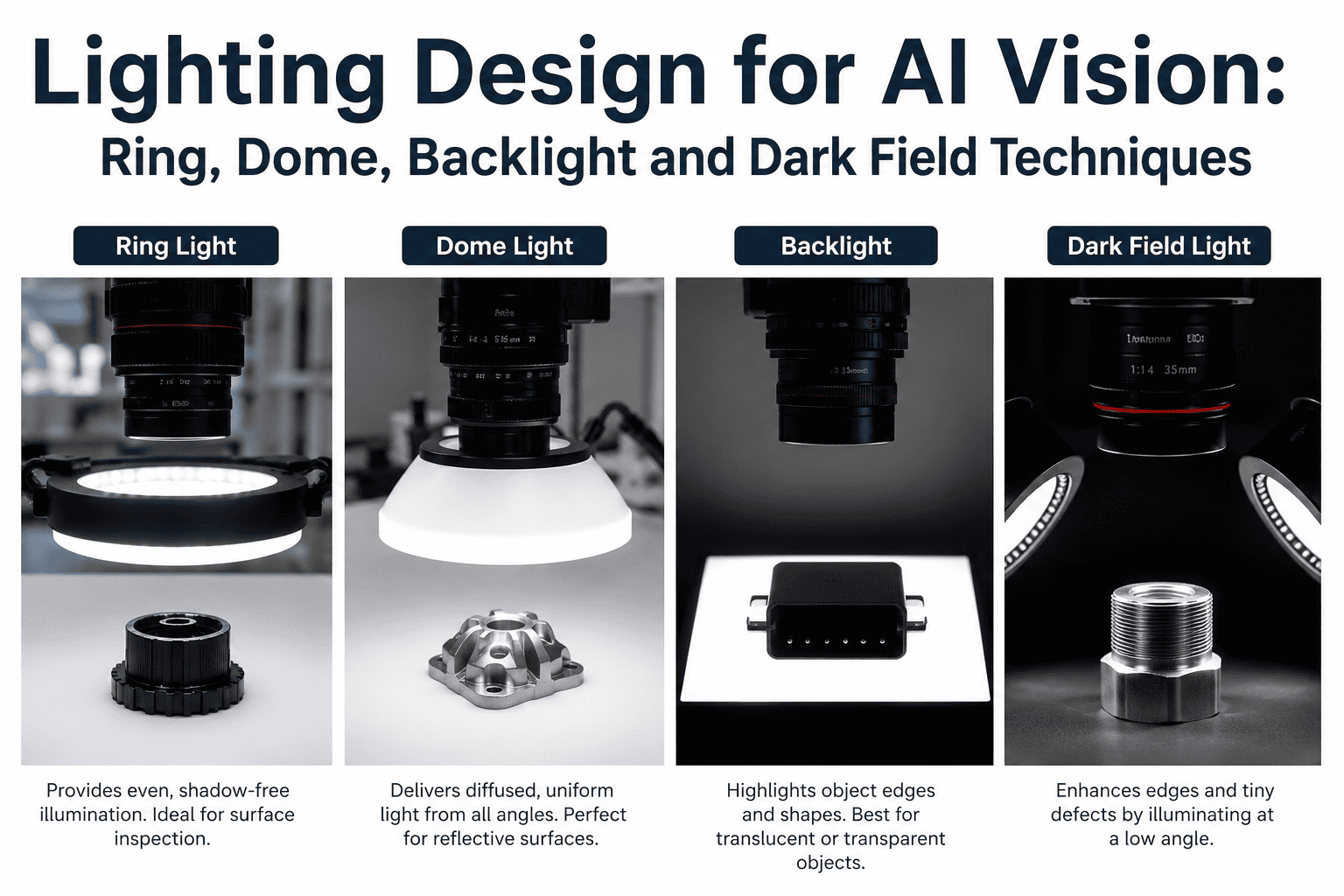
10 itemsHigh-angle front lighting, LED bar or ring, general-purpose. Baseline choice when the part is matte and flat.
Light angle between 0 and 45 degrees to the surface — reveals scratches, engravings, and micro-texture defects.
Diffuse backlight behind the part. Produces black-on-white silhouette for presence, edge, and dimensional gauging.
DOAL through a beam splitter — wafers, PCBs, display panels, mirrored surfaces. Only works with truly flat parts.
Salad-bowl geometry, camera through top opening. Removes glare on automotive parts, plastics, and shiny curved bodies.
Narrow high-intensity strip synchronized with a line-scan camera or short exposure on a fast area-scan.
Laser line projected across the part surface — used to detect dents, warp, or dimensional variation in 3D.
Separate red, green, blue, or near-IR channels used to increase contrast between materials or spot dye defects.
Multiple lights on one station, individually addressable per inspection cycle. Reduces cost of second station.
Defect visibility confirmed on real production samples — good and defective — before mounting hardware.
Positioning, Angle & Mounting
10 items0° for coaxial, 15–30° for darkfield, 45° for brightfield, 90° for backlight — measured with a digital protractor.
Distance adjusted until defect visibility peaks. Distance recorded on the setup form with a photograph.
For linear defects like scratches, light comes from the side perpendicular to the scratch direction.
Light mounted to the same rigid frame as the camera. Vibration blurs illumination the same way it blurs imaging.
Light body, cable, and heatsink confirmed clear of moving parts, product envelope, and safety zones.
Baffles, tunnels, or matte-black shrouds installed to block operator view of the source and stray reflections.
Test image checked for shadows cast by fixtures or the part itself. Second light or diffuser added if needed.
Part moved through the entire inspection window. Contrast holds across the full path, not just at trigger point.
Multiple-angle photos filed against the station ID so future service can restore the exact geometry.
Every adjustment axis locked and painted so any post-installation drift is immediately visible at inspection.
Intensity & Uniformity
8 itemsActual illumination at the inspection surface recorded in lux. Not estimated from datasheet or ambient reading.
Lux readings taken at nine points across the field of view. Max-to-min ratio confirmed within 10 percent.
Exposure set as short as possible to freeze motion. Intensity raised to compensate rather than lengthening exposure.
LEDs pulsed at 2–20x continuous rating for microsecond-scale exposures. Only usable with a strobe controller.
Captured image histogram sits between 20% and 80% of dynamic range. No clipped highlights or crushed blacks.
Full-field image reviewed at 100 percent zoom. Any hot spot or vignette flagged for diffuser or repositioning.
Light not run at maximum. LEDs lose 20–30% output over lifetime; headroom lets automatic compensation absorb it.
Lux readings logged at multiple times across a full production cycle. Any drift beyond 5% investigated.
Color Temperature & Wavelength
6 itemsBlue reveals fine scratches on metal, red blends with red parts, green often best for text OCR. Tested on real defects.
IR penetrates thin plastic, paper, and some food films — used to inspect content inside sealed packaging.
UV excites fluorescent dyes in adhesives, leak indicators, and some contaminants. Eye and skin safety verified.
Color rendering index checked when inspection involves matching or measuring color. Below 80, color reads shift.
Warm white to cool white specified per application. Locked at controller and recorded on setup form.
RGB or multi-channel light sequences programmed and sync'd to camera captures for each defect class.
Ambient Light Control
8 itemsLux readings taken at inspection zone every hour for a full production cycle including all shift changes.
Windows, skylights, and garage doors traced for the seasonal sun path — summer noon is the worst case.
Matte-black shroud or full tunnel around the camera-part-light triangle. Ambient light does not reach the part.
Overhead LEDs and HID lights measured with the inspection light off. Their contribution stays below 5% of source.
Welding arcs, torches, and inspection lamps on adjacent lines evaluated. Baffles or timing separation added if needed.
Stainless guards, polished chutes, or glossy signage matted with black film or repainted flat.
Test images captured at the peak ambient condition. Contrast still meets threshold with worst-case interference.
E-stop and emergency lighting simulated. Confirmed not to falsely trigger inspection or blind the sensor.
Controller & Integration
8 itemsConstant-current — not voltage-regulated — driver used. Prevents thermal runaway and holds intensity as LEDs age.
Light pulse rising edge, width, and delay measured against camera exposure gate. Jitter under 10 microseconds.
Strobe duration set for the shortest exposure that captures the smallest defect at production line speed.
Controller step size fine enough to hold intensity within measurement tolerance. Coarse dimming causes reject spikes.
Each light on its own addressable channel. Sequence programmed for defect-specific illumination cycles.
Trigger, dim, and enable signals wired through the automation layer and confirmed with a full production cycle.
Controller and light thermal cutout verified. LEDs auto-shutdown before permanent damage or color shift occurs.
Any light or controller failure raises an alarm in the CMMS against the station asset — no silent degradation.
Verification & Sign-Off
6 itemsKnown-good and known-defect samples captured under final lighting. Defects clearly visible in the raw image.
Inspection run through two shift changes minimum. Consistent contrast and no ambient-driven false rejects.
Initial lux and controller setpoint archived. Future readings compare against this baseline for aging monitoring.
Technician confirms lights and diffusers can be wiped in under 30 seconds during a normal stoppage.
Cleaning schedule, adjustment lock-out policy, and failure-response steps posted at the station and filed in CMMS.
Both signatures on the lighting verification form. Archived against station ID with all measurements and photos.
Lighting Technique Quick Reference
Use this table as a first-pass technique picker during Phase 02. Always validate on real defect samples before purchase.
| Defect / Inspection Type | Recommended Technique | Typical Angle | Best Wavelength |
|---|---|---|---|
| Scratches on metal / plastic | Darkfield low-angle | 15–30° | Blue or white |
| Presence / edge / dimensional | Diffuse backlight | 180° (behind) | Red or white |
| Reflective flat surface (wafer, PCB) | Coaxial (DOAL) | 0° on-axis | White or green |
| Curved shiny parts (automotive) | Diffuse dome | Full hemisphere | White |
| General flat matte inspection | Brightfield ring or bar | 45–60° | White |
| 3D profile / dent / warp | Structured laser line | 30–45° | Red laser (typ. 660 nm) |
| Through-package content check | Near-IR backlight | 180° (behind) | 850–940 nm IR |
| Adhesive or leak fluorescence | UV flood | 45° | 365–395 nm UV |
Frequently Asked Questions
Which lighting technique should I choose first?
Start from the defect physics — what makes the defect visibly different from a good surface. Scratches and texture need darkfield low-angle lighting. Silhouette and edge measurement need backlight. Shiny curved parts need a diffuse dome. Flat reflective surfaces need coaxial. General matte inspection uses brightfield ring or bar lights. If the defect is invisible to your eye at every angle, no lighting will help — the defect needs a different wavelength or a different inspection modality. iFactory publishes decision worksheets and sample images per technique at the support portal to shorten the selection process.
How much does ambient light really affect inspection accuracy?
Ambient light is the top cause of false-reject spikes correlated to time-of-day patterns. A single unfiltered window can add 500–2000 lux to the inspection zone at midday, easily overwhelming a 200-lux inspection light. Even overhead factory LEDs contribute enough contrast shift to move borderline defect readings across threshold. The fix is almost always mechanical — a matte-black shroud or tunnel around the inspection triangle. Software compensation with the same hardware never fully catches up. Every iFactory deployment specifies a shroud or tunnel by default and verifies contrast at worst-case ambient before sign-off.
Should I use continuous lighting or strobe?
Continuous lighting is simpler and appropriate for stationary parts, low-speed conveyors, and applications where exposure times over 5 milliseconds are acceptable. Strobe lighting is required when motion blur is a risk — high-speed conveyors, robot-mounted parts, or any inspection with an exposure budget under 1 millisecond. Strobe drivers can overdrive LEDs by 2–20 times their continuous rating for microsecond bursts, delivering more light with less heat. iFactory recommends strobe by default for any line moving faster than 100 parts per minute. Book a review to size the right strobe duration for your line speed.
How often do industrial LED lights need replacement?
Quality machine-vision LEDs are rated for 50,000–100,000 operating hours to L70 — the point where output has fallen to 70 percent of new. In a two-shift factory that translates to roughly 5–10 years of service. Actual replacement should happen sooner, driven by measured intensity drift rather than clock time. When the lux reading at the part plane drops beyond the 20 percent headroom reserved at commissioning, replace the light. Log lux readings quarterly against the deployment baseline. Full inspection and cleaning guidance is on the support site.
Can I retrofit lighting on an existing vision installation?
Yes, but retrofit lighting almost always exposes camera and mount decisions that need revision too. If a retrofit adds a diffuse dome, the camera has to look through the top — its position and working distance may need to shift. If backlight is added, part fixturing changes to expose the silhouette. Plan retrofits with the camera placement checklist alongside this one. iFactory retrofit projects walk both checklists together to catch dependencies before hardware is ordered, and the vision team publishes a combined retrofit worksheet on the support portal.
Get Your Lighting Setup Audited Before Model Training
Share your defect samples, current setup photos, and captured images — iFactory engineers validate technique, angle, intensity, and controller integration and return a signed sign-off pack before training data capture begins. Deployments across automotive, food, pharma, electronics, and heavy manufacturing.