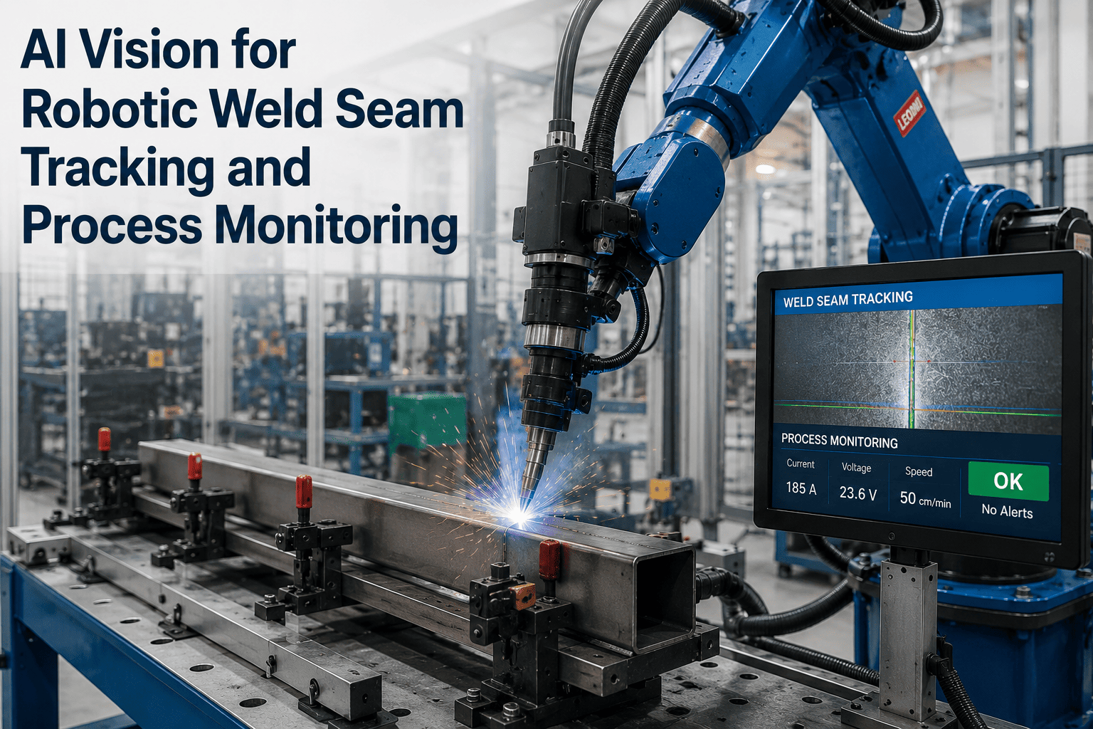
A robot arm is only as accurate as the path it was taught, and the path it was taught assumes the part sits exactly where the CAD model says it should. In real production, it never quite does — fixture wear shifts a joint half a millimeter, thermal expansion pulls a seam sideways as the weld pool heats the surrounding metal, and part-to-part tolerance means no two workpieces present the exact same seam twice. A robot that can't see is welding blind against that drift. See how iFactory's AI vision tracks the weld seam in real time and corrects the robot's path as the joint moves, eliminating the defects that positional drift causes on every taught-path system.
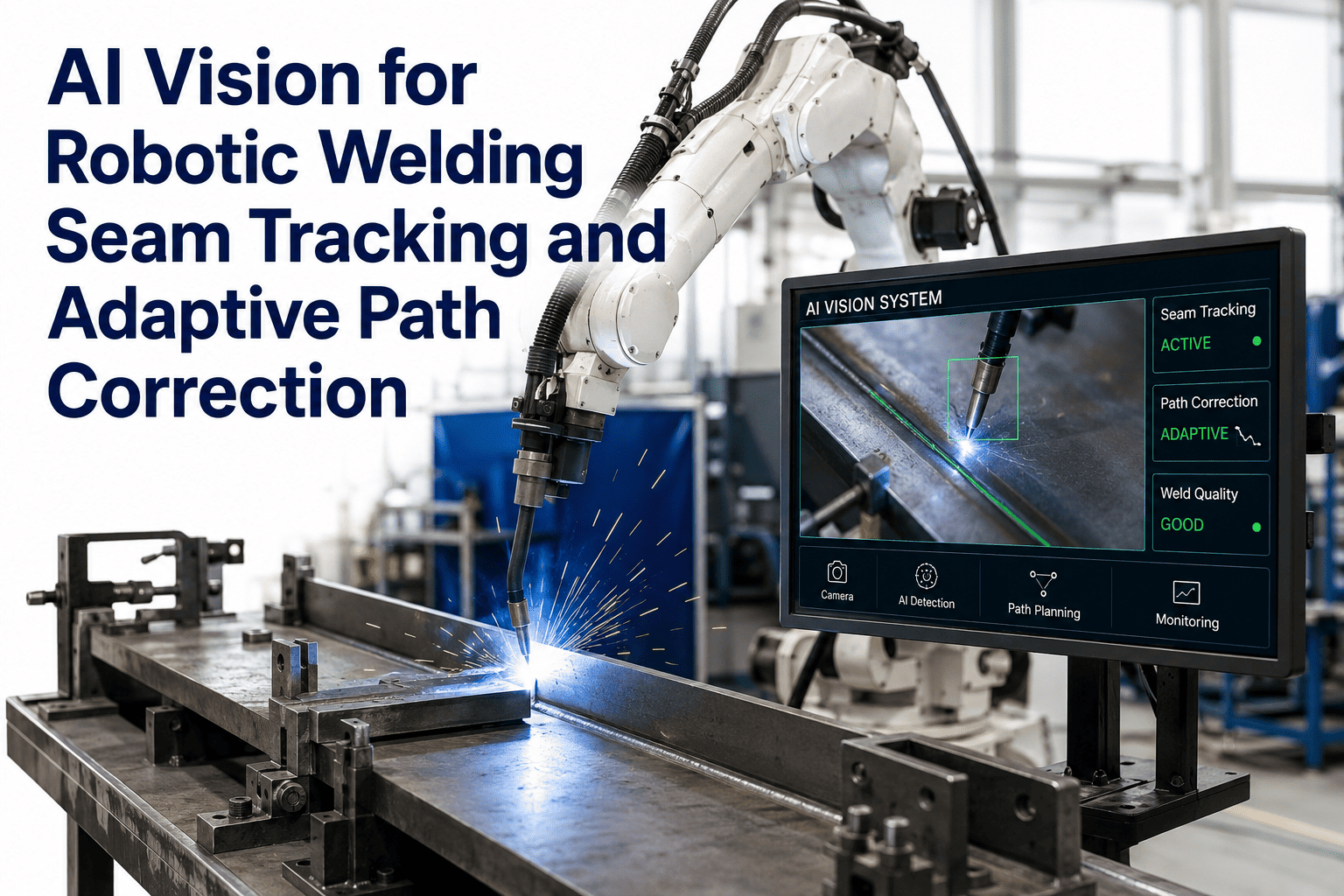
AI Vision for Robotic Welding Seam Tracking and Adaptive Path Correction
Cameras positioned ahead of the torch read the actual seam position continuously, feeding corrected coordinates to the robot controller as thermal distortion, fixture wear, and part tolerance pull the joint away from its taught path.
The Robot Follows the Program — The Joint Doesn't Care
A conventional robotic welding cell is programmed once, in an offline simulation or a teach-pendant session, against a part that was perfectly positioned and perfectly formed. Every weld after that first one is executed blind, on the assumption that this part will sit exactly where the first one did. In practice, three forces conspire against that assumption on nearly every production run: fixture wear gradually loosens the tolerance that held the first part in place, part-to-part dimensional variation means no two blanks from the same stamping or cutting process are identical, and thermal distortion physically deforms the workpiece as heat from the weld pool spreads through the surrounding metal — sometimes shifting the remaining seam by more than the weld bead itself is wide.
A taught-path robot has no way to know any of this happened. It executes the program exactly as written, placing the torch precisely where the seam used to be rather than where it actually is now. The result is a category of defect that has nothing to do with weld parameters, wire feed, or shielding gas — it's simple positional drift, and it is one of the most common and most preventable sources of rework in robotic welding.
The problem compounds on longer seams and higher-heat processes. A short tack weld barely has time to distort the surrounding material before the arc is already off. A long structural seam, or a process that runs at high heat input to maximize deposition rate, gives thermal distortion far more time to accumulate as the weld progresses — which is precisely why the defects from uncorrected drift tend to cluster toward the tail end of long seams, well past the point where the operator who taught the program was watching closely.
Seam Finding vs. Seam Tracking
A static search that runs before welding begins. The sensor scans the joint once, locates the precise start point and overall path, and shifts the robot's entire program to align with where the part actually is — correcting for fixture and positioning error before a single arc strikes.
Continuous, real-time correction while welding is in progress. The sensor scans just ahead of the torch and feeds joint position data to the controller constantly, adjusting the path on the fly to compensate for thermal distortion that develops as the weld itself progresses.
Most production defects that survive a well-executed seam-finding setup come from the second category — distortion that develops after the arc has already started, when a static pre-weld scan can no longer help. That's the gap adaptive path correction is built to close.
From Camera to Corrected Coordinate, in Milliseconds
A sensor mounted 20 to 50 millimeters ahead of the torch — far enough to avoid arc glare and heat damage, close enough to see the joint before the robot reaches it — continuously images the seam.
A laser line is projected onto the joint, and the camera observes how that line distorts across the seam profile, calculating exact depth and lateral position through triangulation geometry.
The measured joint position is compared against the taught path, extracting the exact lateral and depth deviation at that point along the seam — the correction vector the robot needs to apply.
Because the sensor sees ahead of the torch, the correction vector is stored and applied precisely when the torch physically reaches that point on the part — not when the sensor first saw it.
The robot controller applies the correction in real time, shifting the torch to follow the actual seam rather than the originally taught coordinates, without slowing the weld or stopping the arc.
This entire cycle repeats continuously, dozens of times per second, for the full length of the seam — which is what distinguishes real seam tracking from a single pre-weld correction. A part that drifts progressively as it heats up gets a progressively adjusted path, point by point, rather than one static correction applied at the start and assumed to hold true for the rest of the weld.
Track the Real Seam, Not the Taught One
iFactory's AI vision corrects the robot's torch position continuously as the seam shifts from thermal distortion and part variation — eliminating drift-driven defects before they happen.
Five Defect Types Traced Back to an Uncorrected Path
The torch runs alongside the joint rather than directly on it, depositing weld metal onto the base material instead of fusing the actual seam — a defect invisible on the robot's own status display since it executed the program correctly.
Gap width that varies from what the program assumed — wider in one section, tighter in another — leaves sections of the joint under-filled or unfused, often undetectable until destructive testing or a downstream failure.
As heat accumulates and the part physically deforms mid-weld, later sections of a long seam can drift enough that the torch angle and standoff distance are no longer correct for the joint geometry actually present.
When part tolerance closes a gap tighter than the taught program expects, uncorrected heat input burns through thinner sections instead of adjusting parameters to the joint that's actually present.
Bead width and reinforcement height vary along a single seam as standoff distance drifts, creating a weld that passes visual inspection at one point and fails dimensional spec twenty centimeters later.
Why Reflective Metals Need a Different Approach
Not every material presents the seam the same way to a vision sensor. Standard red laser sensors work reliably on most steel, but reflective metals — aluminum, stainless steel, and polished surfaces common in battery enclosures, food-grade tanks, and automotive body panels — reflect red light specularly, effectively blinding a standard sensor the way a mirror would. Blue laser sensors, operating in the 405 to 450 nanometer range, generate cleaner diffuse reflections off these same reflective surfaces, keeping tracking stable on exactly the materials where red-laser systems lose the seam.
Weld spatter and arc glare present a second challenge that has nothing to do with material reflectivity. The laser stripe the sensor depends on can be partially blocked or distorted by spatter during welding, which is why modern vision-based tracking pairs the raw sensor feed with filtering and deep learning models trained specifically to extract a clean seam signal from noisy, partially obscured image data — rather than assuming the camera's raw view is always clean.
Joint type adds a third layer of variability that the extraction algorithm has to handle. Butt joints, fillet joints, lap joints, and V-groove joints each present a fundamentally different profile shape to the sensor, and a system tuned only for one joint geometry will misread the others. Production cells running a genuinely mixed product line need extraction logic trained across the specific joint types they actually produce, not a single generic profile assumed to generalize across every configuration on the floor.
What Adding Vision-Guided Tracking Actually Requires
Adaptive path correction is designed to sit alongside the robot controller your welding cell already runs, not replace it. The sensor package mounts to the torch assembly, and the correction data feeds into the existing motion controller as a real-time offset rather than requiring a new robot program architecture. Most industrial robot brands and welding power sources already support the communication protocols needed to accept this kind of live correction, since seam tracking systems have been integrated across dozens of robot brands and welding platforms for years.
The practical setup work centers on calibrating the sensor's field of view to the specific joint geometries your cell produces — butt joints, fillet joints, lap joints, and V-groove joints each present a different profile to the camera, and the extraction algorithm needs to be tuned to recognize the specific types running through your cell rather than assuming a single generic joint shape. For cells running a narrow, repeatable product mix, this calibration is typically a one-time setup; for high-mix cells, the system can hold multiple joint profiles and select the correct one automatically based on the part being welded.
From Inspection-Dependent Quality to Correction-Dependent Quality
Instead of catching drift-caused defects at final inspection or destructive testing, the correction happens during the weld itself — shifting quality control from a downstream catch to an upstream prevention, before the part ever leaves the cell.
Because thermal distortion accumulates as a weld progresses, uncorrected long seams often show their worst defects in the final third. Continuous tracking corrects for that accumulation in real time instead of letting it compound uninterrupted.
Fixtures that would otherwise need frequent maintenance or replacement to hold tight tolerance can run longer between service intervals, since the vision system compensates for the positional drift that fixture wear introduces.
A single taught path handles more part-to-part variation without requiring a fresh teach cycle for every batch, since the system is actively correcting for the variation rather than depending on the program being exactly right every time.
Frequently Asked Questions
Eliminate Positional Drift Before It Becomes a Rejected Part
iFactory's AI vision tracks weld seams continuously and corrects the robot's path in real time, so thermal distortion and part variation stop showing up as defects on the finish line.