A robot completes its cycle — a weld fires, a screw drives, a pick-and-place lands a component on a PCB — and in the fraction of a second before the fixture releases and the next part enters, the cell has a choice to make. Either the operation was good and the part moves downstream, or something drifted and that part is now scrap waiting to be discovered three stations later, or worse, three months later when a customer opens the box. Every robotic cell without inline verification is running on this hope. AI vision cameras close the loop by inspecting the operation immediately after the robot performs it, classifying the defect at inference time, and routing the part to the correct disposition — pass, rework, or scrap — before the fixture ever opens. That's the difference between a robotic cell that produces defects and one that catches them. Talk to iFactory's robotics vision engineering team to see how the loop closes on your specific cell architecture.
Robotic Guidance · Closed-Loop QC
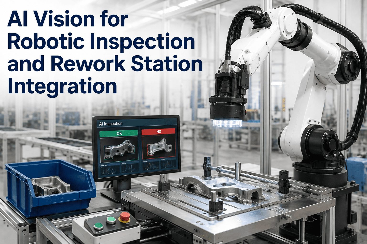
AI Vision for Robotic Inspection and Rework Station Integration
AI cameras inspect every part immediately after the robotic operation, classify defects at inference time, and route items automatically to pass, rework, or scrap disposition. Closed-loop quality inside the robotic cell — no downstream discovery, no batch rework trains, no defect escapes to final assembly.
Closed-Loop Cell Benchmarks
98–99%
Defect detection accuracy
40%
Rework reduction typical
<50ms
PLC reject decision latency
25%
Throughput lift in year one
The Escape Cost Problem
Every Undetected Defect Multiplies Downstream
Manufacturing quality economics follow a rule that is depressingly consistent across industries: a defect caught at the source costs a single dollar to correct, the same defect caught at final assembly costs a hundred, and the same defect caught by the customer costs a thousand or more. That multiplier is what makes closed-loop inspection at the robotic cell so valuable — not the cost of the inspection itself, but the escape it prevents.
Traditional robotic cells inspect at the end of the line, if they inspect at all. A weld that failed to penetrate at the body-in-white station gets discovered at final quality audit, after the body has passed through paint, trim, chassis, and door-hanging. By that point the rework is not a single joint — it's disassembly of everything that was mounted downstream, tear-out of paint and sealant, re-welding under conditions the station was never designed for, and re-processing of every downstream operation. The single-dollar defect became a thousand-dollar rework because nobody caught it in the cell that produced it.
Human visual inspection cannot close this gap at production speed. Even skilled inspectors miss twenty to thirty percent of defects under real conditions, and accuracy degrades fifteen to twenty-five percent after two hours of continuous observation. The human eye and brain are not the right instruments for verifying thousands of robot-produced operations per shift against sub-millimeter tolerances. AI vision is — deep learning models achieve ninety-eight to ninety-nine percent detection accuracy at full line speed and never fatigue, never blink, and never miss the last defect of the shift because they were watching the clock.
The Closed-Loop Architecture
How AI Vision Actually Closes the Loop Inside the Robotic Cell
A closed-loop robotic quality cell is not a camera bolted on next to a robot. It is a coordinated sequence of hardware and software layers that inspect the operation, classify the outcome, decide the disposition, and physically route the part — all within a single production cycle. The six stages below are the sequence every mature deployment follows, regardless of whether the underlying operation is welding, assembly, painting, or pick-and-place.
01
Robot Completes Operation, Signals Vision
The robot controller sends a completion signal over PROFINET, EtherNet/IP, or hard-wired I/O the moment the operation finishes. The vision system is waiting for that trigger — it does not scan continuously, it inspects the specific part the specific robot just worked on, tied to a part serial number the MES tracks through the cell.
↓
02
Camera Captures Under Controlled Illumination
2D area cameras, 3D stereo pairs, or structured-light profilers capture the region of interest with dedicated LED or laser illumination. Lighting geometry is engineered per operation — coaxial for glossy surfaces, dark-field for surface texture, structured light for dimensional verification. The image is not a photograph, it is a measurement.
↓
03
Edge AI Inference in Milliseconds
A CNN or YOLO-variant model running on an edge GPU or NPU processes the image locally in the cell — no cloud round-trip, no network latency. The model outputs pass or fail plus a defect class, a location within the frame, and a confidence score. The full inference completes in single-digit to low-tens of milliseconds, well inside the takt time budget.
↓
04
PLC Reads Verdict and Fires Routing Actuator
The vision system publishes the verdict to the cell PLC over the same fieldbus the robot uses. The PLC is what actually decides the physical routing — it has the deterministic, sub-fifty-millisecond response time that a network-attached MES simply cannot deliver. Reject gate, diverter conveyor, robot pick-off, or hold fixture fires against the correctly tracked part.
↓
05
Defect-Class Routing to Rework or Scrap
Not every defect is a scrap defect. The AI classifies the defect type — cosmetic scratch, dimensional deviation, missing component, weld porosity — and the PLC uses that classification to route differentially. A cosmetic issue goes to a manual rework buffer for touch-up. A dimensional deviation goes to the automated rework robot for re-work. An unrecoverable structural defect goes to scrap. No human inspector re-decides in the middle of the loop.
↓
06
MES Logs Event, SPC Feeds Back to Robot
The MES receives the full event — work order, serial, station, recipe, verdict, defect class, image reference, timestamp — via OPC-UA or MQTT to the historian. When defect rates for a specific class start trending against threshold, the SPC layer feeds parameter corrections back to the robot: weld schedule adjustment, torque re-calibration, pick-point offset. The loop is now closed at both physical routing and process control levels.
See Closed-Loop Vision on a Live Cell
Watch a Robotic Weld, Inspect, and Route Cycle Run Under 60 Seconds
iFactory's robotics vision team walks you through a live cell demo — camera capture, edge AI inference, PLC routing to rework, and MES event logging — running against real production footage. Bring your cell layout and we'll map the integration points for your specific PLC, robot, and MES stack.
Defect Classification Matrix
The Routing Decision Depends on the Defect Class
The reason to invest in AI vision over a rule-based pass-fail sensor is that AI can distinguish defect types, and defect type is what determines whether a part goes to rework, scrap, or a hold buffer for engineering review. A cosmetic defect on a Class-A surface may be reworkable in five seconds at a manual touch-up station. The same nominal defect on a hidden structural member may not warrant rework at all. The routing matrix below reflects the standard disposition logic across major robotic cell types.
| Defect Class |
Detection Method |
Typical Routing |
Feedback to Robot |
| Missing Component |
2D object detection, template matching |
Automated rework — robot re-picks and places |
Log pick failure, check feeder alignment |
| Dimensional Deviation |
3D structured light, stereo triangulation |
Rework robot re-torques or repositions |
Adjust robot end-effector offset, tool wear check |
| Weld Porosity / Undercut |
3D imaging, thermal signature analysis |
Automated re-weld or scrap by severity |
Adjust weld schedule, check consumable feed |
| Surface Scratch / Paint Blemish |
Deep learning surface anomaly detection |
Manual touch-up buffer, released after rework |
Check fixture wear, review upstream handling |
| Assembly Sequence Error |
Multi-frame verification against work order |
Hold fixture, engineering review |
Halt station, verify recipe against work order |
| Foreign Object / Contamination |
Anomaly detection, unexpected-object CNN |
Scrap or clean-and-re-run per severity |
Log contamination source, trigger cell cleaning |
| Adhesive / Sealant Gap |
Laser profilometry, bead width measurement |
Automated dispense re-run |
Adjust dispenser flow, temperature, nozzle wear |
The matrix is the actual product engineering that gets configured during deployment. Each defect class maps to a detection method, a routing action, and an upstream corrective signal — and the mapping is specific to the cell, not a generic industry default. Getting this matrix right is what separates a vision system that documents failures from one that closes the loop.
Integration Architecture
How the Vision, PLC, Robot, and MES Layers Actually Communicate
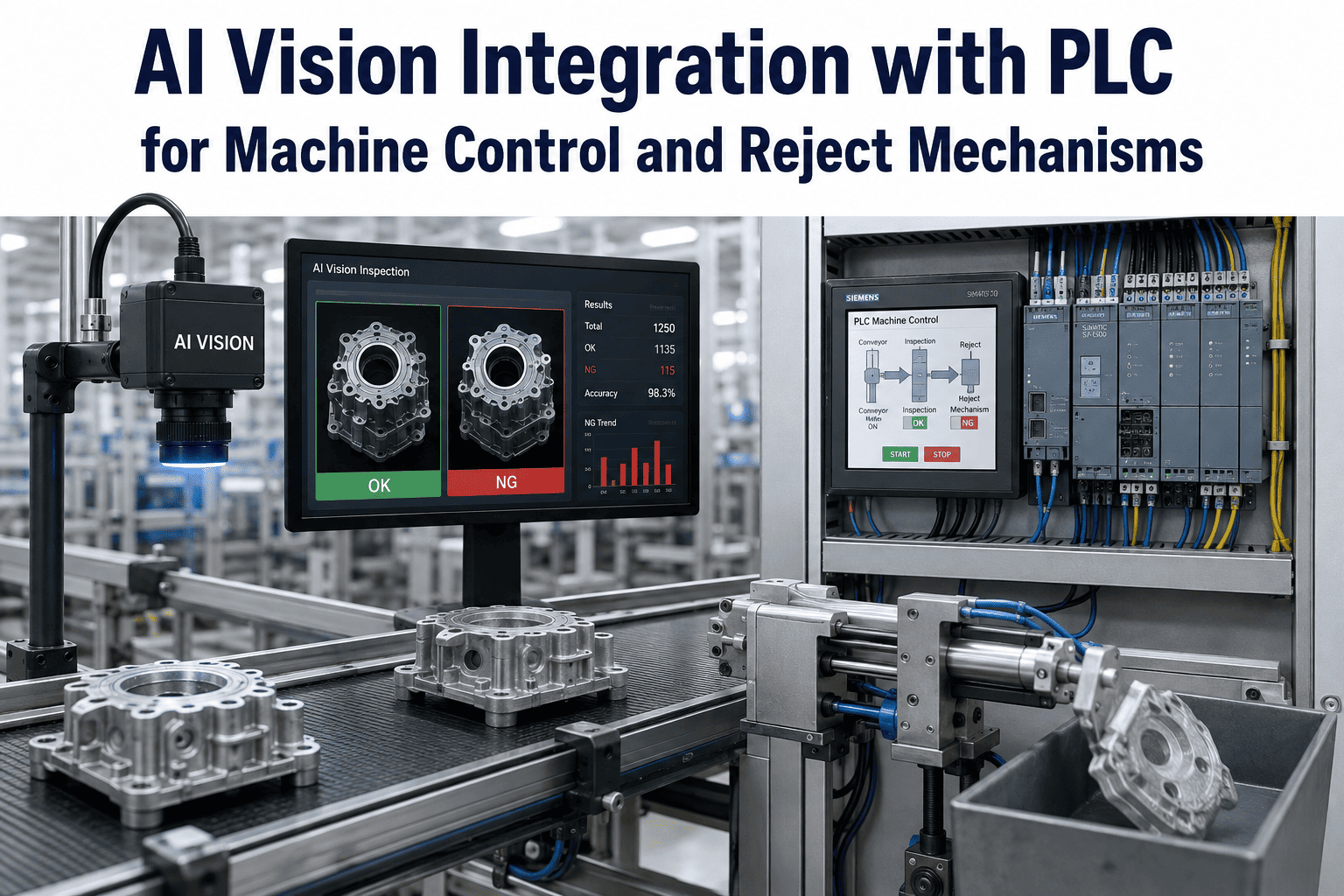
A common failure mode in robotic vision deployments is treating the integration as a single connection between the camera and the MES. That architecture cannot deliver the deterministic sub-fifty-millisecond routing decision the cell needs. The correct architecture separates the fast in-loop decision path from the slow contextual logging path, and runs them in parallel over different protocols.
In-Loop Decision Path
Camera → PLC → Actuator
The pass/fail verdict and defect class travel from the vision system to the cell PLC over PROFINET, EtherNet/IP, or EtherCAT — deterministic fieldbus protocols with millisecond-class response guarantees. The PLC executes the physical routing decision within a single production cycle. No cloud, no MES round-trip, no ambiguity about timing. This path is what makes closed-loop control work.
PROFINET
EtherNet/IP
EtherCAT
<50ms latency
Contextual Data Path
Camera → MES → Historian
The full event payload — image reference, defect class, confidence score, work order, serial number, operator ID, upstream station data — travels to the MES and historian over OPC-UA or MQTT, in parallel with the fast decision path. This is the record that feeds SPC dashboards, model retraining datasets, warranty traceability, and audit compliance. It doesn't need millisecond latency, but it needs to capture every event.
OPC-UA
MQTT
REST API
Historian DB
Feedback Path
SPC → PLC → Robot Recipe
When SPC dashboards detect a drift pattern in defect rates, the correction flows back to the robot as a recipe adjustment — weld current change, torque setpoint shift, pick-point offset re-calibration. The MES writes the new recipe parameter to the PLC, which pushes it to the robot controller. This is the process-control closure that reduces defects at source rather than just catching them at inspection.
SPC drift alerts
Recipe write-back
Digital twin sync
Model retraining
The three-path architecture is the reason mature deployments hit the sub-fifty-millisecond routing decision while also maintaining full event traceability and continuous model improvement. Trying to run everything through a single OPC-UA connection to the MES is the classic mistake that stalls integration projects at the proof-of-concept stage.
Cell Application Coverage
Closed-Loop Vision Across Every Major Robotic Cell Type
The closed-loop architecture generalizes across cell types, but the specific detection method and routing logic change with the operation. Below are the most common robotic cell applications where AI vision has replaced end-of-line inspection with in-cell closed-loop control.
Spot Weld Verification
Body-in-white · Automotive OEM
Ultrasonic and 3D imaging inspect every weld nugget for penetration, diameter, and spatter. Defective welds route to an automated re-weld robot or a hold fixture for teardown review. Weld schedule drift feeds back to the welding controller within hours rather than shifts.
Pick-and-Place Verification
PCB assembly · Electronics
2D object detection and OCR confirm every component is placed, oriented, and identified correctly. Missing or misoriented parts route back to the pick-and-place robot for re-work before reflow. Feeder alignment drift is caught before it produces a batch of unrepairable boards.
Adhesive and Sealant Beads
Assembly · Automotive, appliances
Laser profilometers measure bead width, height, and continuity across the entire dispensed path. Gaps or overflow trigger automated re-dispense at a rework station. Nozzle wear, viscosity drift, and temperature variation all get caught before they produce leak-path failures.
Screw and Torque Verification
Assembly · Powertrain, appliances
Vision confirms every fastener is present, seated, and correctly driven. Torque signature analysis pairs with visual inspection to catch cross-threaded, under-driven, or missed fasteners. Failed positions route to an automated re-drive robot or manual rework buffer.
Paint and Coating Inspection
Finishing · Automotive, appliances
Deflectometry and deep learning surface analysis catch runs, orange peel, dust inclusions, and coverage gaps before the panel leaves the booth. Defective areas route to a manual polish or spot-repair station. Booth environmental drift correlates back to defect patterns.
Machined Part Dimensional
Machining · Precision manufacturing
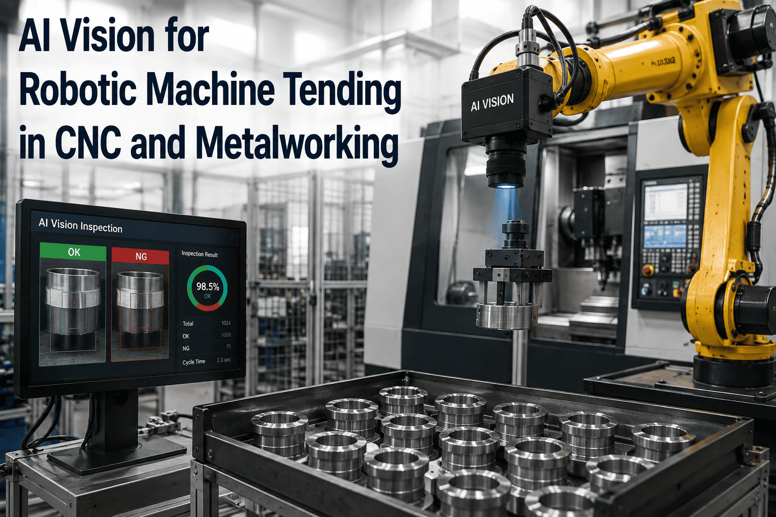
Structured light and stereo vision perform GD&T-compliant measurement at cycle times under 500ms per part. Parts outside tolerance route to a re-work fixture or scrap based on deviation magnitude. Tool wear patterns feed back to CNC offset adjustments within hours.
Turnkey Deployment
Live in 6–12 Weeks with the Full iFactory AI Bundle
iFactory ships closed-loop robotic vision as a pre-configured turnkey bundle — pre-racked NVIDIA AI server, edge inference hardware, software pre-loaded, cabling and integration scope defined upfront. The physical install is: rack it, plug in power, plug in Ethernet, and the AI is live. What follows is model training against your specific defect library, PLC integration, and operator handover.
Weeks 1–4
Ship, Rack, Network, Data Capture
Turnkey AI server arrives pre-configured and racked. Cabling to cell PLC and MES, network handshake verification, and initial image dataset capture from your live production. Vision hardware mounted on cell fixtures per engineering layout.
Weeks 5–8
Model Training and Shadow Pilot
CNN and YOLO-variant models trained against captured defect examples. System runs in shadow mode alongside existing inspection — measuring every part but not yet routing. Accuracy validated against ground truth, and routing logic proven at the PLC level.
Weeks 9–12
Go-Live and Operator Training
System takes over primary inspection and routing responsibility. Cell operators trained on the AI dashboard, defect classification review workflow, and escalation paths. SPC dashboards go live to quality engineers and cell supervisors. 24×7 remote monitoring by the iFactory support team begins.
1000+Clients on iFactory platform
99.9%Platform uptime SLA
24×7Remote AI monitoring
6–12wkLive production timeline
Documented Outcomes
What Closed-Loop AI Vision Actually Delivers in Year One
The numbers below reflect documented outcomes from AI vision deployments in automotive, electronics, and general manufacturing published across 2025–2026 industry sources. They are the target range mature deployments hit — not the maximum, and not a marketing floor.
60%
Defect Escape Reduction
Defects caught inside the cell that would previously have escaped to final assembly or the customer. The dominant driver of first-year ROI for most deployments.
40%
Rework Volume Reduction
Automated in-cell rework replaces disassembly at downstream stations. The rework that remains happens at the correct station, with correct tooling and time budget.
25%
Throughput Improvement
Fewer stopped-line rework interruptions, faster in-cell decisions, and elimination of end-of-line inspection queuing all compound into meaningful throughput gains.
99%+
Detection Accuracy at Line Speed
Deep learning models consistently exceed human inspector accuracy — and unlike inspectors, they never fatigue, never blink, and process every part with the same rigor as the first.
20–35%
Overall Defect Rate Reduction
Gartner's analysis of AI in manufacturing identifies closed-loop quality as the highest-ROI application, delivering this range of defect reduction within twelve months of deployment.
12–18mo
Typical Payback Period
Full payback on the vision system from rework labor savings, scrap reduction, warranty avoidance, and throughput gains combined. Aggressive deployments in high-defect-cost environments recover the investment inside a year.
Common Questions
Frequently Asked Questions
How is the routing decision fast enough to happen inside a single production cycle?
The reject decision runs on the cell PLC, not on the MES or the cloud. The vision system publishes the pass/fail verdict and defect class to the PLC over deterministic fieldbus — PROFINET, EtherNet/IP, or EtherCAT — with millisecond-class response guarantees. Edge AI inference on a local GPU or NPU completes in single-digit to low-tens of milliseconds, and the PLC fires the reject gate, diverter, or robot pick-off within a total budget of under fifty milliseconds from operation completion. That's what makes closed-loop routing work at real line speeds.
Talk to robotics engineering about your specific takt time and PLC architecture.
How does the AI distinguish between defect classes rather than just pass/fail?
Modern deep learning models for industrial inspection are multi-class classifiers, not binary detectors. A CNN or YOLO-variant model is trained on labeled examples of each defect class the cell needs to distinguish — missing components, dimensional deviations, weld porosity, surface scratches, and so on — and outputs both the class and a confidence score for every inference. The PLC uses that class label to select the correct routing action from the pre-configured defect matrix, sending cosmetic defects to manual touch-up and structural defects to automated rework or scrap. The classification is what turns raw detection into actionable disposition without requiring a human re-inspection step in the middle of the loop.
What happens if the AI model is uncertain — a low-confidence verdict?
Low-confidence predictions fall through to a pre-configured fault protocol agreed with the controls engineer at design time. The typical options are reject by default, pass by default, stop the line for operator review, or route to a manual inspection buffer. The choice depends on the consequence of an escaped defect against the cost of a stoppage, and it is set per defect class and per cell. Low-confidence events are also flagged in the historian for engineering review — persistent uncertainty on a specific defect type is a signal that the model needs additional training data for that class, and the iFactory team handles the retraining cycle as part of the 24×7 support scope.
Book a demo to walk through fault protocol configuration.
Can the system handle multiple part types on the same cell?
Yes, and this is one of the most common deployment patterns for mixed-model cells. The vision system stores multiple inspection recipes and switches between them automatically based on barcode scans, PLC recipe numbers, or automatic part identification through pattern matching. Adding a new part variant to an existing cell installation typically requires new defect image capture and model retraining, not new hardware — the same cameras, edge inference server, and PLC integration cover the full mix. The AI models adapt to new variants as more production data accumulates, and multi-recipe support is standard on the iFactory platform.
How does the system integrate with existing MES and ERP without ripping out our infrastructure?
The vision system publishes event data through standard industrial protocols — OPC-UA, MQTT, and REST APIs — that virtually every modern MES and ERP already supports as input. The event payload includes work order, serial number, station ID, recipe, verdict, defect class, image reference, and timestamp, which the MES associates with production records and forwards to the ERP for aggregate quality reporting. In-loop routing runs on the PLC and doesn't touch the MES, so integration is additive rather than disruptive — the existing controls architecture keeps working exactly as it did, and the vision layer plugs into it. The iFactory turnkey scope includes integration engineering as a defined line item, not a discovery phase.
Close the Loop in Your Cell
Turnkey Robotic Vision, Live in 6–12 Weeks
iFactory's closed-loop robotic vision platform ships as a pre-configured turnkey bundle — hardware racked and ready, software pre-loaded, integration scope defined upfront, and 24×7 remote monitoring included. Rack it, plug in power and Ethernet, and closed-loop quality is live on the cell. Get a turnkey AI quote with the twelve-week delivery timeline, or start with a six-week pilot on a single cell to prove the loop before scaling.