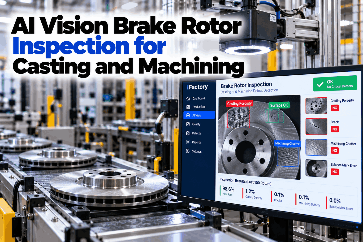
AI Vision Brake Rotor Inspection for Casting and Machining

By Josh Brook on October 22, 2026

ai-vision-brake-rotor-inspection-casting-machining

A brake rotor is a gray iron casting that has to survive heat, load and thousands of stops, and one disc with a hidden crack or a misplaced balance cut can reach a vehicle long before anyone notices. Brake rotor inspection today spans several stations, each with its own gauge, checklist or tester. AI vision adds one camera view at each station and a single record per disc, so a defect can be traced to where and when it was made. See how a held disc is traced in a short rotor vision demo.

AI VISION · BRAKE ROTORS

Every Brake Disc Checked at Every Station, From Casting to Final Mark

iFactory Vision Defect Detection puts cameras at casting, machining, balance and final stations. The AI flags each disc, links any defect to the station and shift that made it, and holds suspect parts before they ship.

Disc A2417 · Station 6HOLD
Vented front disc · Shift B · final camera
Pore clusterHat-side friction face
Chatter bandOuter ring · finish lathe 2
Crack indicationNear hat radius · to eddy current
Balance cut14° from balancer record
Held automatically · release by quality engineer only
ROTOR ANATOMY

Five Zones Where a Vented Rotor Can Go Wrong

Gray iron is used for rotors because it conducts and stores heat well, and its graphite flakes damp vibration. Many rotors are specified to SAE J431 G3000, a pearlitic grade with a hardness range of 187 to 246 HB. SAE researchers note that iron within one grade can still vary widely in microstructure, and that variation on the friction surface affects noise. Defects tend to gather in a few zones of the part. In one published failure analysis, a crack ran around most of the hat-to-plate neck and started at sand inclusions. Ask our support team which zones your drawing treats as critical.

01
Mounting face and bolt holesFlatness and hole position are gauged. The camera checks for burrs, chips and casting skin on the seat.
02
Neck, hat to plateA thermal and mechanical stress point, so a known crack zone. Hat wall casting defects show here too.
03
Friction facesFinish, chatter, open pores and inclusions after machining, seen by one camera per face.
04
Vanes and cooling channelCore shift, blocked vents, fins and broken vanes, visible at the outer edge.
05
Outer edgeWhere the balancer mills material away to correct imbalance.
GRAY IRON CASTING DEFECTS

Eight Brake Disc Surface Defects and How Each One Is Handled

Each card shows where a defect starts, what a camera actually sees and the usual first response. Rotor casting porosity and sand inclusions start at the mould. Chatter starts at the lathe: a CNC lathe cuts spiral grooves into each friction face, and a patent on rotor finishing links uneven grooves to pad movement, noise, pedal pulsation and uneven wear. The final call on any disc always follows your drawing and boundary samples. Walk through your own defect list in a defect library session.

CASTING
Gas porosityGas trapped at pouring. The camera sees round, smooth pits on cast or machined faces.Hold if on a friction face
CASTING
Shrinkage porosityPoor feeding at thick sections. Jagged, branching cavities show once machining opens them.Hold and notify foundry
CASTING
Sand inclusionMould or core sand swept into the metal. Angular grains or rough pockets with a different texture.Hold, link to mould line
CASTING
Cold shutTwo metal fronts meet too cold to fuse. A smooth-edged seam line on the hat or edge.Hold, confirm before release
CASTING OR SERVICE LOAD
CrackStress at the neck, hot tears, inclusions as starters. The camera sees open linear indications only; tight cracks need NDT.Hold, route to eddy current
CASTING
Vane core shiftVent core moved or floated in the mould. Uneven vent openings around the outer edge.Hold, gauge plate thickness
MACHINING
Chatter and tool marksTool wear, loose clamping or fixture vibration. A regular banded pattern or broken lay on the face.Hold back to last good disc
BALANCE
Balance cut errorWrong angle, depth or cut count. Cut position and size checked against the correction record.Re-check on balancer
BRAKE ROTOR INSPECTION BY STATION

Six Stations, One Record per Disc

A defect is cheapest to stop at the station that made it. In production, rotors are spun to measure imbalance, and the balancer works out where and how deep to mill the outer edge. One patent notes that uneven vanes from core wash can make that cut inaccurate and force a re-cut, which is why balance mark verification belongs in the flow. Map your own stations with our support team.

1CastMould and core condition, pour records tied to each casting
2Shakeout and cleanCold shuts, sand burn-on, fins in vents, core shift at the edge
3Rough machinePores and shrinkage opened by the first cut
4Finish machineChatter bands, tool marks and lay on both friction faces
5BalanceCut present, cut count and angle match the correction record
6Mark and finalCode readable, matches MES, last full-surface look

Know Which Station and Shift Made the Bad Disc

iFactory links every flag to the station, machine and shift that produced it, holds suspect discs automatically and feeds the result into your control plan records. Your quality team gets a clear scope instead of a full-day sort.

Rotor line · Quality engineer and iFactory
Quality engineerWhy is disc A2417 on hold?
iFactoryThe final camera found a linear indication near the hat radius, and the balance cut sits 14° from the balancer record. Eddy-current result for this serial is pending.
Quality engineerAnything else from that shift?
iFactoryTwo discs from finish lathe 2 on Shift B show the same chatter band. Both are held, with images attached.
DISC RUNOUT CHECK VISION

What the Camera Owns and What the Gauge Owns

A 2D camera does not replace a runout or thickness gauge. Mounted runout on many vehicles is about 0.05 mm or less, and it is measured with a dial indicator or contact probes, not an image. Crack testing on brake discs is commonly done with eddy current, 100% inline, with automatic OK and NOK sorting. Vision works beside these checks and makes sure each result lands on the right disc. See the handshake in a gauge link walkthrough.

CAMERA OWNS
  • Open pores, sand pockets and cold shuts on visible faces
  • Chatter bands and tool-mark patterns on every disc
  • Balance cut present, count and angle
  • Vent openings and fins at the outer edge
  • Marking readable and tied to the disc serial
GAUGE AND NDT OWN
  • Lateral runout and flatness
  • Thickness and thickness variation (DTV)
  • Residual imbalance on the balancer
  • Tight and subsurface cracks: eddy current or magnetic particle
  • Subsurface porosity: X-ray or ultrasound; Ra: profilometer
One record per disc

Serial, gauge values, NDT result and camera images are joined in a single record, so every result can be traced to the right part.

BRAKE COMPONENT PPAP

Where Vision Sits in Your Control Plan

A control plan is a required document in every PPAP submission, and a special characteristic symbol on the drawing triggers mandatory control plan treatment. IATF 16949 asks suppliers to identify special characteristics and to use error-proofing where it fits. For a tier 1 brake supplier, that means vision should be written into the plan as a defined method, not an add-on. The matrix below is illustrative. Your customer's symbols and frequencies decide the real entries. Get a mapping template from our quality support team.

Characteristic
Typical class
Primary method
Frequency
Vision's role
Reaction
Cracks, friction and bolt faces
Safety
Eddy current or magnetic particle
Every disc
Flags open indications, links image to NDT result
Hold, confirm, scope by shift
Lateral runout
Critical
Runout gauge
Per control plan
Confirms the value belongs to this serial
Reject, check fixture
Thickness and DTV
Critical
Multi-probe gauge
Per control plan
Same serial handshake
Reject, review tool offsets
Residual imbalance
Significant
Balance machine
Every disc
Checks cut position and count against the record
Re-balance or reject
Friction face finish
Significant
Profilometer
Sample per shift
Watches every disc for chatter between samples
Hold back to last good sample
Surface porosity and inclusions
Customer defined
Visual with boundary samples
Every disc
Applies the boundary sample the same way each shift
Hold for review
Marking and traceability
Traceability
Code reader
Every disc
Reads code and matches it to MES
Re-mark or quarantine
SAFETY CRITICAL PART INSPECTION

Four Outcomes for Every Camera Flag

A good reaction plan names roles, time limits, containment scope and who has authority to release. A camera flag should follow the same logic every time, so a disc never ships because a busy shift decided it looked fine. The first question is always whether the flag sits on a friction face, the neck or the mounting face. Adapt these outcomes to your own reaction plan in a reaction plan session.

1
ConfirmSafety zone, with a test downstream. Hold the disc, route it to eddy current or the gauge and attach the result to the serial.
2
QuarantineSafety zone, no confirming test. A quality engineer decides, and suspect discs are scoped by station and shift.
3
ReleaseOther zone, matches an accepted boundary sample. The image is kept with the disc record for audit.
4
ReviewOther zone, no boundary sample match. Hold the disc; rework only where the drawing allows it.
TIER 1 BRAKE SUPPLIER QUALITY KPIS

Six Measures Worth Tracking From Day One

Vision records are only useful if someone reviews them. These measures show whether flags are accurate, whether holds are cleared quickly and whether defects are being fixed at the source. Set your own targets from your baseline. Ask our support team for a sample weekly review.

Flags per thousand discsBy defect type, station and shift
Flag agreementHow often engineer reviews confirm the camera's call
Hold clearing timeHours from hold to release, rework or scrap
Suspect scope sizeDiscs held per event, ideally one shift or less
Repeat defectsSame defect on the same station within a week
Customer concernsRotor complaints per million discs shipped
COST OF AN ESCAPE

What a Late Catch Costs Compared With a Station Catch

The biggest costs of a brake defect escape, such as warranty, customer chargebacks or a recall, are hard to predict and are left out here. This worksheet sizes only the sorting and containment gap, using assumed inputs and simple arithmetic. Swap in your own figures. Our quality team can help you build a fuller case on a short call.

Discs per shift1,200, assumed
Shifts per day3, assumed
Days in the pipeline before a customer catch4, assumed
Sort cost per disc$0.50, assumed
Freight and admin per late event$3,000, assumed
Escape events per year2, assumed
Late catch cost per event1,200 × 3 × 4 = 14,400 discs × $0.50 + $3,000 = $10,200
Station catch cost per event (one shift)1,200 × $0.50 = $600
Gap per year($10,200 − $600) × 2 = $19,200

This is the difference in sorting scope only. It does not claim every escape is prevented, and it excludes warranty, line-stop charges and recall exposure.

TURNKEY AI DEPLOYMENT

Cameras, Lighting and an Edge Server Ready for the Rotor Line

iFactory delivers Vision Defect Detection as one package. Cameras and lighting are fitted at the stations you choose, and a pre-configured NVIDIA AI server ships racked and ready with the defect models loaded, so images are processed on site. You rack it, plug in power and Ethernet, and the AI is live. To scope your line, ask our support team for a turnkey quote.

What's Included
  • Pre-configured NVIDIA AI edge server, racked and ready
  • Industrial cameras and lighting for cast and machined faces
  • Defect models tuned to your discs and boundary samples
  • Links to gauges, balancer, eddy-current tester and MES
  • Automatic hold signals to reject chutes or quarantine racks
  • Disc records by serial, station and shift
  • 24×7 remote monitoring of models and hardware
Live in 6–12 weeks
Wk 1–4
Stations and Samples

Stations chosen, cameras and server installed, boundary samples and defect images gathered.

Wk 5–8
Shadow Run

Models run silently beside current checks while quality engineers review every flag.

Wk 9–12
Holds Switched On

Automatic holds enabled, control plan revised, operators and engineers trained.

HOW iFACTORY FITS

Automotive Braking Parts AI Built Around Your Existing Checks

iFactory adds a camera view and a shared record to the rotor line without replacing the gauges and testers your PPAP already relies on. Plan a first-line pilot in a pilot planning call.

1
Flags each disc. Cameras at casting, machining, balance and final stations check every part.
2
Traces the source. Every flag is linked to the station, machine and shift that made it.
3
Holds suspect parts. Discs are held automatically until a test or an engineer clears them.
4
Feeds the control plan. Results and images join gauge and NDT data in one record per serial.
1000+
Industrial clients running iFactory
99.9%
Platform uptime for multi-shift lines
6-12 wks
From racked server to live disc holds
FREQUENTLY ASKED QUESTIONS

What Brake Quality Teams Ask About Rotor Vision

Can AI vision measure rotor runout or thickness variation?
No. Lateral runout, flatness, thickness and thickness variation are measured with contact or laser gauges to the hundredths of a millimetre. A 2D camera cannot do that. What vision adds is a check that each gauge result is stored against the right disc serial, plus a full surface look at every part.
Does it replace eddy-current or magnetic particle crack testing?
No. Tight and subsurface cracks need NDT. The camera flags open linear indications it can see, routes those discs to the crack tester and attaches the result to the disc record. Where the drawing calls cracks a safety characteristic, your existing 100% test stays in the plan.
How does balance mark verification work?
The balancer computes where and how deep to mill the outer edge. A camera after the balancer checks that a cut is present, that the count is right and that its angle matches the correction record. A mismatch sends the disc back to the balancer instead of to packing.
Does FMVSS 135 set rotor defect limits?
No. FMVSS 135 covers service and parking brake performance for light vehicles up to 3,500 kg GVWR, tested at vehicle level. Rotor acceptance limits come from your customer's drawing, specifications and boundary samples, which is what the camera is set up against.
Can the same setup cover calipers and drums?
Often, yes. Brake caliper inspection with AI follows the same pattern: cameras on cast surfaces and machined bores, flags linked to station and shift, and holds on suspect parts. Each part family needs its own images and boundary samples before holds are switched on.
How do we start without disrupting PPAP status?
Run vision in shadow mode first, beside your approved checks, so nothing in the approved process changes. Once flags are reviewed and agreed, revise the control plan and inform your customer as their change rules require. Our support team can plan that first step.

Put a Record Behind Every Disc You Ship

Cameras at each rotor station, flags linked to station and shift, automatic holds and one record per serial alongside your gauges. Delivered turnkey and live in 6 to 12 weeks.

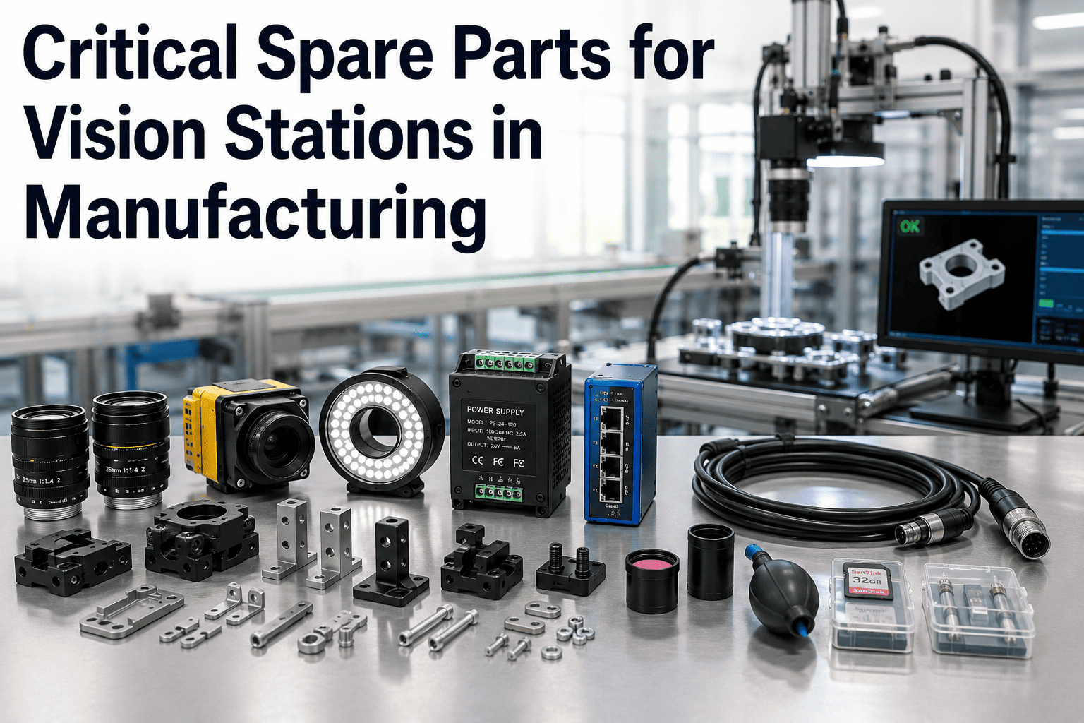
Example disc record · illustration
SerialA2417, Shift B
Stations passed1 to 6, images kept
Gauge valuesRunout and DTV linked
Vision flags2, disc on hold
Release only by quality engineer, logged

Share This Story, Choose Your Platform!