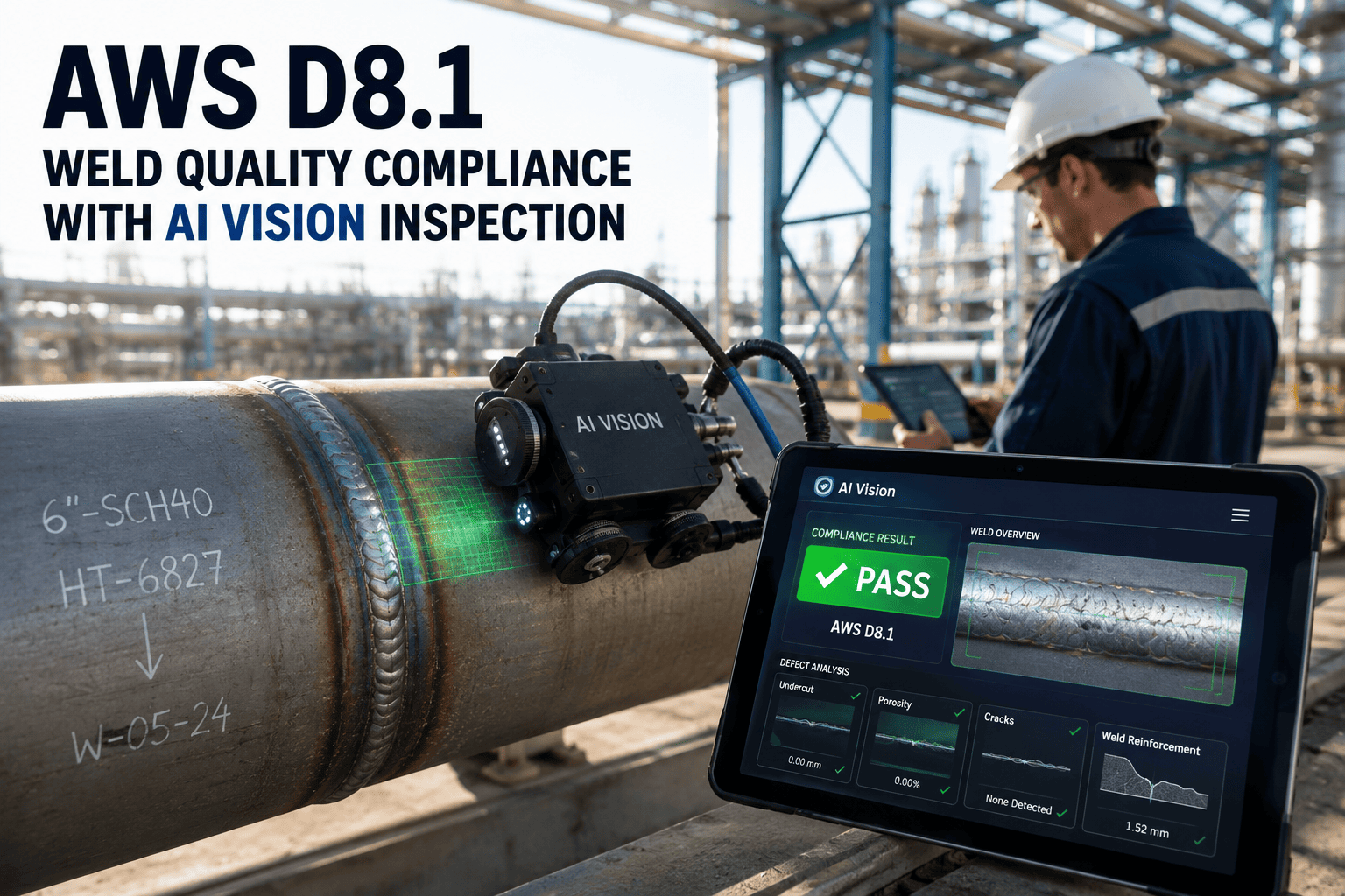
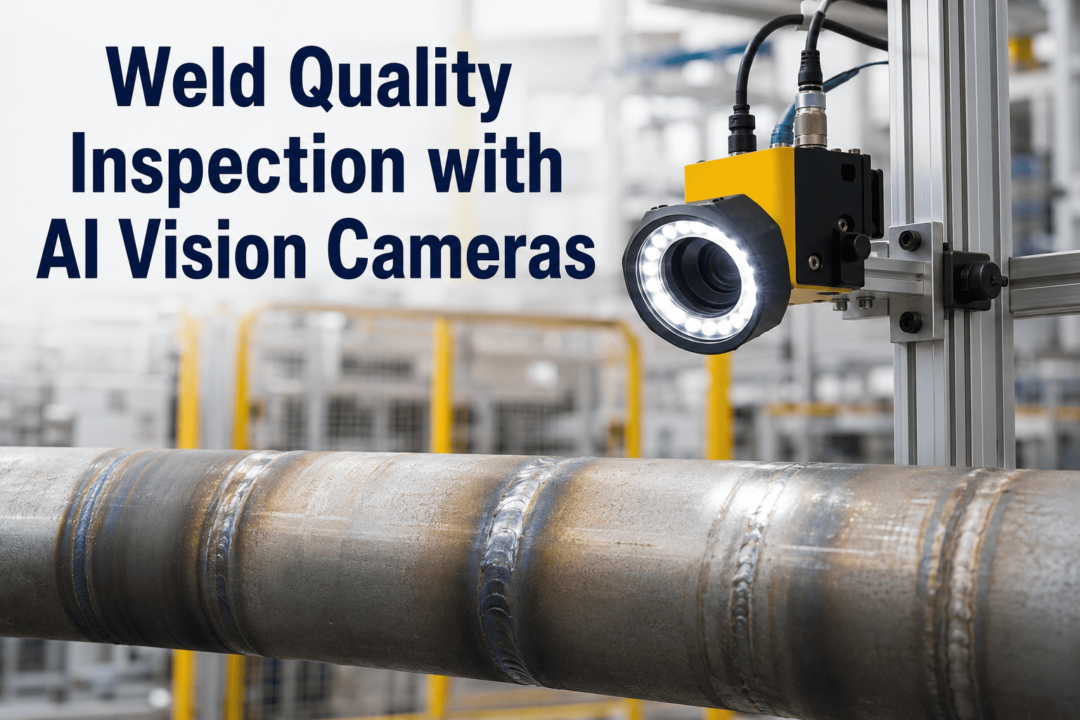
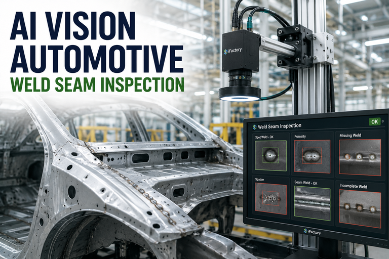
A body-in-white cell lays down thousands of resistance spot welds before a single body reaches the paint shop, and every one of them is either evidence you can trace to a specific station and electrode wear cycle, or it is a statistical assumption you are hoping holds up in a warranty investigation. The gap between those two outcomes is not the camera you buy — it is the checklist you follow the week you install it. Almost every weld inspection deployment that ends up ignored six months later was locked into that fate during the first five days: a lens etched by spatter that nobody protected, a shutter blinded by arc glare, a model trained for MIG being asked to classify laser welds, an AWS D8.1 threshold copied from a spec sheet instead of tuned to the actual gun. This checklist walks you through every phase of a defensible automotive weld inspection rollout, and if you want a working session on any of it before you install, you can book a deployment planning call with our vision team.
Automotive Welding · AI Deployment Checklist
Automotive Weld Inspection Deployment Checklist
Camera protection from spatter and slag, lighting that survives arc glare, weld-type-specific model selection, AWS D8.1 acceptance criteria configuration, and MES integration testing — every phase of a rollout that holds up on a live body shop.
Why This Deployment Is Different From Every Other Vision Rollout
A weld cell is one of the most hostile environments in the plant for a camera. Molten metal ejects at hundreds of meters per second, arcs blind any sensor without proper filtering, spatter etches lens coatings within days if the housing is wrong, and the same joint you inspect on a MIG gun looks nothing like the joint two stations over on a resistance spot cell. Deploying a monitoring rig you would install on a conveyor into a weld cell is how good engineering teams end up ripping out a system in month three. Every step in this checklist exists because it corrects a specific mistake that has cost a real deployment its credibility.
01
Spatter Environment
Molten ejecta will destroy an unprotected lens inside a shift. Air knives, sacrificial glass, and slide covers are not options.
02
Arc Glare
The welding arc is orders of magnitude brighter than the surrounding cell. Wrong exposure means a black frame for the entire weld.
03
Process-Specific Defects
MIG porosity, spot weld indentation, and laser seam profiles need different models. One model for all welds catches nothing well.
04
Code-Traceable Decisions
A pass or fail with no traceability to AWS D8.1, D8.8, or D8.14 acceptance criteria will not survive a first customer audit.
How To Use This Checklist
This checklist is organized into six deployment phases that follow the actual rollout sequence on a real weld cell. Work through Phases 1 to 3 during install week, Phase 4 during model configuration, Phase 5 as you wire up MES and quality systems, and Phase 6 as the go-live gate that decides whether the system becomes a trusted layer of the quality program or a monitor nobody looks at. Every phase includes explicit checkboxes so nothing gets deferred to memory.
1
Camera Protection From Spatter
3
Camera Angles Per Weld Type
4
Model Selection & AWS D8.1 Criteria
5
MES & PLC Integration Testing
6
Go-Live Validation Gate
Phase 1: Camera Protection From Spatter Checklist
This is the phase that decides whether your cameras are still working in month two. Every downstream calibration, every training run, every threshold you tune is worthless if the lens is etched translucent by weld ejecta within the first week. The mistake most sites make is treating the enclosure spec as a purchasing decision instead of a survival decision. Spatter is not dust. It arrives at high velocity, still molten, and it welds itself to whatever surface it hits.
Camera housing rated for the specific spatter direction and travel distance from the arc
Sacrificial protective glass installed in front of the lens, not the lens itself exposed
Protective glass replacement schedule defined in shifts, not months
Air knife or purge line installed to keep smoke and fume off the optical path
Air supply confirmed clean, dry, and independent of general shop air where possible
Motorized or pneumatic slide cover installed for cameras adjacent to the arc
Slide cover cycle timed against actual weld cycle, not a generic delay
Housing thermal rating verified against measured cell temperature at mount location
Cable jackets rated for spatter contact and routed away from ejecta trajectories
Mount vibration-isolated from robot base and stinger movement
Access path for glass replacement confirmed without dismounting the whole camera
Not sure your current camera housings will survive first-week spatter on a live line? Talk to our team about a housing spec review before you install.
Phase 2: Lighting Configuration For Arc Glare Checklist
The welding arc is the brightest thing in the plant, and any exposure setting bright enough to see it will render everything else in the frame as absolute black. Any exposure setting that captures the surrounding joint will be saturated to white the instant the arc strikes. Correct weld inspection lighting is not about adding lumens — it is about controlling when the camera looks, what wavelength it sees, and how it handles the millisecond transition between arc-on and arc-off.
Inspection strategy defined per weld — pre-weld, post-weld, or during-arc capture
Post-weld capture timed to trigger after arc-off and before robot moves away
Neutral density or band-pass optical filter selected if inspecting during arc
High dynamic range camera specified where arc and cool joint share the same frame
Dedicated inspection lighting selected — not relying on cell ambient or robot task lights
Lighting wavelength chosen to reveal target defect — blue for surface, IR for thermal signature
Structured light or laser line specified where bead profile and undercut depth matter
Reflection off shiny sheet metal tested and diffused where it saturates the sensor
Lighting fixture housing rated for the same spatter environment as the camera
Exposure and gain locked per weld type — no auto-exposure drifting between joints
Weld Type Coverage Matrix
| Weld Type | Primary Defects | Camera Setup | Governing Standard |
| Resistance Spot |
Undersized nugget, expulsion, indentation depth, missing weld |
Overhead + angled surface view of the impression |
AWS D8.1M (steel), D8.2M (aluminum) |
| MIG (GMAW) |
Porosity, undercut, spatter density, cold lap, inconsistent bead |
Post-arc bead capture with structured light profile |
AWS D8.8M (steel), D8.14M (aluminum) |
| TIG (GTAW) |
Tungsten inclusion, oxidation, incomplete fusion |
Close-range post-weld optical, controlled ambient |
AWS D8.8M |
| Laser Seam |
Concavity, humping, keyhole collapse, seam gap |
Coaxial and off-axis synchronized capture |
AWS D8.17M (laser welds in steel) |
| Laser Spot |
Missed shots, offset, insufficient penetration |
Post-shot high-resolution overhead |
AWS D8.17M |
Phase 3: Camera Angles Per Weld Type Checklist
Different weld processes present their defects at completely different scales, angles, and moments in the cycle. A camera position that is perfect for scoring a spot weld indentation is useless for capturing MIG bead ripple pattern, and a camera aimed correctly for a laser seam profile cannot see the crater at the start of a MIG pass. This phase forces a per-weld-type placement decision instead of a one-size-fits-all mount.
Resistance Spot Welds
Camera positioned perpendicular to the sheet surface at the electrode contact point
Field of view sized so the full electrode impression fills the frame consistently
Secondary angled view where indentation depth measurement is required
Robot-mounted or fixture-mounted decision made based on cell access
Trigger tied to weld gun open signal, not to a fixed timer
MIG And TIG Welds
Camera positioned to view completed bead from a low angle, not directly overhead
Field of view covers the full bead length in a single capture where possible
Structured light line projected across the bead for profile and undercut measurement
Capture timed after arc-off but before the operator or robot moves the joint
Laser Welds
Coaxial camera aligned with laser head axis for weld pool and keyhole monitoring
Off-axis camera positioned for seam gap measurement ahead of the weld pool
Post-weld overhead capture for final seam profile inspection
Optical filters matched to the specific laser wavelength in use
Multiple Weld Types On The Same Line?
Body-in-white cells mix spot, MIG, and increasingly laser welds on the same body — and each needs its own camera setup, its own model, and its own AWS acceptance table. Our team has scoped this against production lines running all three simultaneously, and can walk your specific joint mix during a working session before any hardware ships.
Phase 4: Weld Type Model Selection And AWS D8.1 Criteria Configuration Checklist
A generic weld model treats every bead the same and produces an inspection layer with no defensible link back to the codes your customer contracts already require. AWS D8.1M for resistance spot welds in steel, D8.2M for aluminum spot welds, D8.8M for arc welds in steel, D8.14M for arc welds in aluminum, and D8.17M for laser welds each define specific acceptance criteria — minimum nugget diameter, allowable indentation depth, permitted porosity, and permissible surface indications. Every one of those criteria has to be mapped into the model configuration or the pass/fail decision will not stand up to a customer audit.
Weld type inventory built for the cell — every joint classified as spot, MIG, TIG, or laser
Material combination documented per joint — steel, coated steel, AHSS, aluminum
Governing AWS D8 standard identified per weld type and per material
Process-specific model selected per weld type, not one generic model for the whole cell
Minimum acceptable weld size configured per material thickness combination
Maximum allowable indentation depth configured per AWS D8.1 table for the joint stack
Class A, B, or C weld classification recorded for every joint under D8.8 or D8.14
Porosity size and distribution limits set per governing code, not per rule of thumb
Undercut depth threshold set to code limit, not to whatever the model defaulted to
Missing weld and mis-located weld detection enabled where the code requires it
Baseline training set collected covering every joint variant in the cell inventory
Fine-tuning completed against known good and known defective samples from your own line
Pass or fail decision explicitly traceable to a cited AWS D8 clause per weld
Defect Detection Coverage
Porosity
Gas pockets in the weld from contaminated wire, poor shielding, or moisture. Model quantifies size and distribution against code limits.
Undercut
Groove melted into base metal beside the bead. Structured light measures depth against permissible AWS limits.
Spatter Density
Ejected droplets around the joint. Excess density signals wrong parameters and threatens paint adhesion downstream.
Missing Weld
Robot programming error or skipped shot. Detected by comparing captured weld count against the programmed sequence.
Undersized Nugget
Spot weld indentation below minimum diameter for the joint stack thickness. Direct code violation under AWS D8.1.
Expulsion
Molten metal ejected during a spot weld from excess current. Distinct visual signature model can classify per joint.
Phase 5: MES And PLC Integration Testing Checklist
A weld inspection system that generates a beautiful pass or fail on a screen nobody reads is a very expensive light show. Integration is the phase that turns a monitoring rig into a quality gate — every decision has to route to the MES with a VIN, a station ID, a weld count, a timestamp, and a link back to the captured evidence. Every reject has to trigger a PLC action or a work order that a human owns. Skipping this phase is why so many inspection deployments end up disconnected from the line they were meant to protect.
MES protocol confirmed — OPC UA, MQTT, direct database, or plant-standard middleware
Every weld inspection result linked to VIN or body ID at the station level
Weld sequence number logged so a specific gun-cycle can be recalled in an audit
Welding parameters — current, voltage, time — captured alongside the visual result
Captured image or video clip archived and retrievable via the MES record
Reject signal wired to PLC where automatic hold or rework routing is required
CMMS work order generated for repeated rejects at the same station or gun
Electrode wear tracking synchronized so tip dress cycles correlate to defect trend
Latency measured end to end — camera trigger to MES record — and confirmed within takt
Failover behavior tested — network drop should not release rejected bodies downstream
Data retention window matches customer contract and warranty period requirements
Audit trail confirmed — who acknowledged, who overrode, and when, all recorded
Struggling to fit inspection results into an existing MES without breaking VIN traceability? Our integration team has done this against most major automotive MES stacks.
Phase 6: Go-Live Validation Gate Checklist
Go-live on a weld inspection system is not the day the cameras start capturing. It is the day quality signs off that the system can be trusted to make pass or fail decisions on production bodies without a human double-check on every weld. That is a much higher bar, and it requires a validation gate that runs against known defects, known good welds, and a parallel period where the AI decision runs alongside your existing inspection so the two can be compared honestly. Skipping this gate is how a system ends up quietly ignored while the plant keeps running sample-based inspection in the background.
Known-defect samples run through every camera — porosity, undercut, missing, undersized
Known-good samples run in matched quantity to measure false reject rate
Parallel run against existing sampling or destructive test for one full production week
Detection accuracy measured per weld type, not averaged across the whole cell
False reject rate confirmed low enough that operators do not learn to override
Every AWS D8 clause referenced in the criteria configuration tested against a sample
Operator training completed — how to review a reject and how to escalate
Quality team training completed — how to pull evidence for a customer audit
Ownership documented — who tunes the model going forward, who owns lens replacement
Handover sign-off only after a full week with zero unresolved false rejects
What The Fully Deployed System Delivers
Per-Weld
Pass or fail decision on every joint, linked to VIN and station
Code-Cited
Every decision traceable to a specific AWS D8 clause and threshold
Auditable
Image evidence and welding parameters retrievable per body, per weld
Common Deployment Mistakes To Avoid
Every weld inspection rollout eventually collects the same short list of installation regrets. Reviewing them before you drill your first mount is cheaper than living with any one of them for a year.
Mounting a camera without a sacrificial glass and watching the lens etch out in a week
Using auto-exposure and getting a black frame every time the arc strikes
Running one generic weld model for spot, MIG, and laser and getting weak performance on all three
Configuring thresholds from a spec sheet without mapping them to AWS D8 clauses
Going live without VIN-linked storage and finding out at the first customer audit
Skipping the parallel run so quality never trusts the AI decision at handover
Leaving no clear owner for lens replacement and losing capture quality gradually
Frequently Asked Questions
Which AWS standard should our AI weld inspection criteria be configured against?
The right standard depends on the process and material of each joint in the cell, and most automotive lines end up configuring against several at once. AWS D8.1M governs resistance spot welds in steel, D8.2M covers spot welds in aluminum, D8.8M covers arc welding of steel, D8.14M covers arc welding of aluminum, and D8.17M covers laser welds in steel. Every pass or fail decision the system makes should trace back to a specific clause in the applicable standard, so it stands up in a customer audit. If you want help mapping your weld inventory to the correct standards, our team can walk it with you on a
demo call.
How is the camera protected from spatter without constantly cleaning the lens?
Every camera in the cell sits behind a sacrificial protective glass that takes the spatter hits so the lens does not, and that glass is on a defined replacement schedule measured in shifts rather than months. High-spatter positions get an additional pneumatic slide cover that closes during the arc and opens only for the inspection capture window, along with an air knife or purge line to keep smoke and fume out of the optical path. The camera itself is mounted in a housing rated for the specific spatter environment of that position, not a generic industrial enclosure.
Talk to our team if you want us to review your specific cell layout before you specify housings.
Can one AI model inspect every weld type in the cell?
No, and this is one of the most common deployment mistakes. Resistance spot welds, MIG beads, TIG beads, and laser seams each produce completely different visual signatures — bead ripple, indentation depth, oxidation color, keyhole geometry — and a single model asked to classify all of them ends up weak at every one. Deployments that hold up in production use process-specific models per weld type, fine-tuned against sample welds from the actual cell during commissioning. This is standard practice on every serious automotive rollout and the reason our platform ships separate models per process.
Does inspection have to slow the line down or extend takt time?
Not when the inspection is designed to run inside the natural pause between weld cycles rather than as a separate station. Post-arc capture completes in the fraction of a second between arc-off and the robot moving to the next joint, and the pass or fail decision is available before the next weld starts. On resistance spot lines the inspection typically completes 180 welds per minute with no takt impact at all. Deployments that add takt time are almost always the ones that treated inspection as a bolt-on station instead of integrating it into the existing cycle.
How long does a full weld inspection deployment take from survey to trusted go-live?
A typical single-cell deployment runs six to twelve weeks from site survey to trusted production alerts, with roughly two weeks of survey and housing design, three to six weeks of installation, camera calibration, and model fine-tuning against your sample welds, and one to two weeks of parallel validation against your existing quality process before formal handover. Multi-cell rollouts across a full body shop stagger cell by cell so quality sees results on the first cell while later cells are still in survey. If you want a scoped timeline against your specific line,
book a demo and we can walk it in a working session.
Turn This Checklist Into A Working Weld Inspection Program
Our team can walk this entire checklist against your specific weld cells, joint mix, and MES environment, starting with a free deployment review that maps camera positions, spatter protection, AWS D8 criteria mapping, and integration testing before any hardware ships. Six to twelve weeks from survey to trusted, code-cited pass or fail decisions routing straight into your quality system.