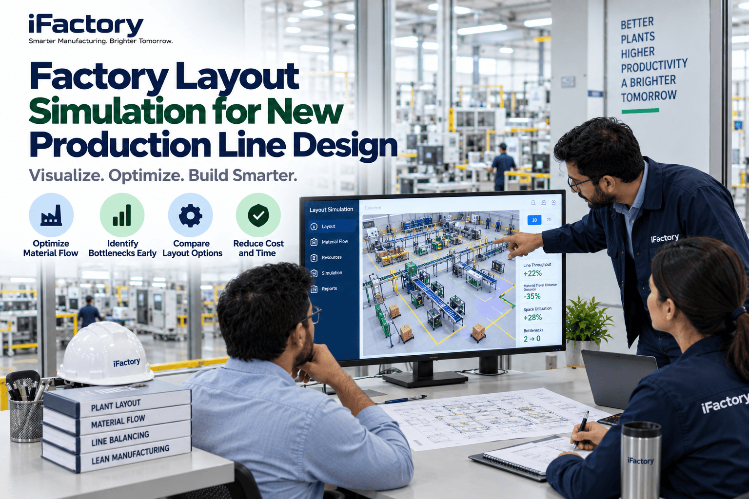
Concrete gets poured long before anyone models how material will actually move. Static 2D floor plans and CAD renderings tell designers whether equipment fits within a footprint — they cannot predict throughput, bottlenecks, queue lengths, cross-flow conflicts, or the effect of variability on flow. Discrete event simulation (DES) does. Case studies of layout redesign with FlexSim, AnyLogic, Simio, or Arena consistently show throughput gains of 40-65% from flow reconfiguration alone — gains that arrive because the simulation surfaced problems while they were still cheap to fix. Factory layout simulation is not a nice-to-have for major projects; it is the discipline that keeps design decisions honest against system dynamics that no drawing can represent.
iFactory / Factory layout simulation
Simulate Material Flow Before You Pour Concrete
Discrete event simulation for new production line and factory layout design — throughput prediction, bottleneck identification, material travel optimization, and cross-flow conflict resolution before construction commits.
Bottleneck station
St-12 wait
Cross-flow conflicts
14 → 0
3D DES
material + resource
Pre-concrete
not post-build
The Problem in Factory Layout Planning
A typical plant expansion or new line project runs on 2D CAD drawings and engineering judgement. The design team spaces equipment based on footprint and aisle width, routes material based on process sequence, and commits the layout to construction. Six months later, the line runs and reveals problems the drawings could not show — a bottleneck at inspection because two upstream lines converge into one queue, a material handler with an unsustainable step count, cross-flow conflicts at forklift aisles that force stops nobody predicted. Fixing these post-construction costs 10-100x what fixing them pre-construction would have. And the fixes rarely reach root cause because the concrete is already poured.
Where Layout Decisions Actually Fail
Factory layout failure modes are consistent across greenfield builds, brownfield expansions, and line replacements. Each is a specific DES-detectable issue that CAD alone cannot surface.
Convergence bottleneck
Two upstream lines converge into one downstream inspection or packaging station. Static drawing shows the station fits. Simulation shows queue lengths that would strand a shift of production every day.
Material travel excess
Layout groups equipment by function rather than by flow. Material handler step count 40% above target. Only surfaces post-construction — layout redesign not economically viable at that point.
Cross-flow conflict
Forklift aisles cross main material paths at high-frequency intersections. Traffic-jam moments unpredictable from static drawings. Simulation surfaces the interference pattern before the aisles are painted.
Variability blind spot
Design assumes average cycle time. Reality has cycle variability that creates transient queues invisible to static analysis. Simulation with variability distributions shows what really happens.
What Good Looks Like in Layout Simulation
A working layout simulation practice holds four disciplines together — 3D DES model against realistic data, scenario comparison across options, integration with facility design tools, and simulation output driving design decisions.
3D DES Model
Discrete event simulation model of the proposed layout with equipment, material flow, workers, and material handling equipment (forklifts, AGVs, conveyors). Variability distributions applied where relevant.
Variability included
Scenario Comparison
Multiple layout options simulated in parallel. Throughput, WIP, travel distance, bottleneck location, and utilization compared quantitatively. Design decision made on data, not preference.
Options compared
CAD Integration
Facility design tools (Autodesk Factory Design Utilities, AutoCAD, Inventor, Revit) bidirectionally synchronized with the simulation model. Layout changes propagate; nothing is rebuilt from scratch.
Sync, don't rebuild
Decision-Driving
Simulation output feeds design decisions before commit. Scenarios that fail throughput or WIP targets return to design. Only validated layouts move to construction.
Validated then poured
How iFactory AI Fits
iFactory AI works alongside FlexSim, AnyLogic, Simio, and Arena — providing the operational data feed that keeps simulation models grounded in current-state performance and the KPI framework that translates simulation output into design decisions.
Data Grounding
Simulation + Analytics
Current-state cycle times, changeover durations, breakdown patterns, and material handling times sourced from MES and equipment historians. Simulation calibrated against reality, not idealized data.
Scenario Runner
Simulation Layer
Multiple layout scenarios run and compared with consistent KPI framework — throughput, WIP, travel distance, utilization, bottleneck identification. Design team reviews evidence, not opinions.
CAD Bridge
Simulation + Design
Bidirectional integration with facility design tools. Layout iterations in CAD carry into simulation without model rebuild. Simulation-driven design changes carry back to CAD.
Design Gate
Simulation + Project
Design gate review requires simulation validation against project KPIs before construction release. Gates without validated simulation defer to next review cycle.
Ask your plant engineering manager how the last new line's layout was validated before construction. If the answer is "engineering judgement and 2D CAD," the operational problems it now runs with were preventable at pilot cost. Book a layout simulation review.
12-Week Layout Simulation Pilot on One Project
One active or upcoming layout project (new line, expansion, or major rearrangement), twelve weeks. The pilot builds a DES model against real data, compares scenarios, and produces the design decision brief.
Weeks 1–3
Data + Baseline
Current-state data collected from MES and historians. Baseline layout modeled and validated against known throughput. Design intent for new layout captured from project team.
Weeks 4–7
Scenario Build
Multiple layout scenarios built with variability distributions. Scenario comparison run. Bottleneck and travel-distance analysis for each option. Design team joint review.
Weeks 8–10
Design Iteration
Scenarios that fail KPIs returned to design team. Iteration cycle with layout changes propagated between CAD and simulation. Validated scenarios advance.
Weeks 11–12
Design Brief
Final validated design brief with simulation evidence. Construction release approved. Rollout to remaining projects in the capital pipeline scoped.
Who Owns the KPI
Layout simulation crosses plant engineering, operations, project management, and finance. Each function owns a specific KPI or the simulation becomes an academic exercise disconnected from the project.
Plant Engineering Manager
Layouts validated before construction
Owns the design discipline — the share of layout projects with simulation validation before construction release. Projects without validation carry preventable operational cost.
Operations Lead
Post-construction operational shortfall
Owns the operational outcome — the gap between designed throughput and achieved throughput 90 days after go-live. Rising gap signals design validation is missing.
Project Manager
Design change orders post-construction
Owns the project economics — the count and cost of design change orders after construction commits. Simulation-validated designs generate far fewer.
CFO / Finance
Capital efficiency vs pro forma
Owns the capital outcome — actual output per capital dollar vs pro forma. Layout-driven shortfalls destroy pro forma economics; validation protects them.
FAQ
Which DES platform is best — FlexSim, AnyLogic, Simio, Arena?
Each has strengths. Autodesk FlexSim leads on 3D visualisation and integration with Autodesk Factory Design Utilities, AutoCAD, Inventor, and Revit — strong choice when the design team already runs Autodesk stack. AnyLogic combines DES with agent-based and system dynamics modelling, valuable for logistics and supply chain analysis alongside layout. Simio and Arena carry heritage in academic and industrial simulation with strong statistical rigour. Rockwell Arena integrates natively with FactoryTalk. The right choice depends on integration priorities and modelling scope — the workflow supports whichever your engineering team uses rather than requiring platform migration.
How much operational data do we need to build a credible simulation?
Enough to represent variability where it matters — cycle time distributions rather than averages, breakdown MTBF/MTTR distributions rather than uptime averages, changeover duration distributions rather than nominal SMED times. For a new line with no operational history, historical data from similar lines or benchmark data from equipment vendors provides the starting point; the model calibrates as the line runs post-go-live. For a brownfield expansion, existing line data from MES and equipment historians provides the calibration base directly. The simulation does not need perfect data to be useful — it needs data honest enough about variability to surface the problems averages hide.
Book a demo to see the data calibration approach.
How does this handle brownfield expansion — layouts constrained by existing structure?
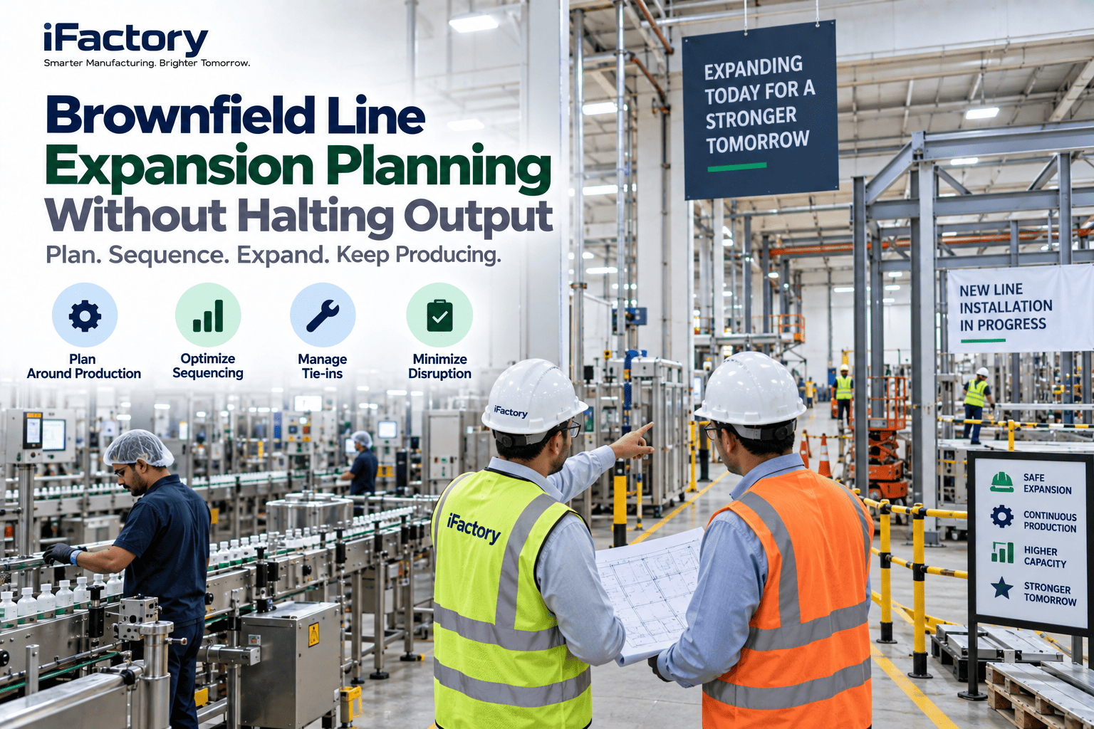
Brownfield expansion is where layout simulation delivers the most value because constraints are severe and design errors most expensive to fix. The existing building envelope, structural columns, utility routing, and operational lines constrain the design space in ways greenfield does not. Simulation surfaces the specific constraints most likely to create bottlenecks — a proposed line that adds handling traffic to an already-congested aisle, a new inspection station that would create a queue upstream of a validated line, a material staging area that would extend forklift travel beyond a sustainable step count. Where simulation is not run for brownfield, these constraints reveal themselves only post-construction — and the workarounds accumulate as chronic operational cost.
Stop discovering layout problems after the concrete is poured.
Simulate One Active Layout Project — Live
Bring one active layout project (new line, expansion, or major rearrangement) with the current CAD, project KPIs, and cycle-time data from any comparable running lines. We'll build a starter DES model, run scenario comparison, and demonstrate the design decision-support the platform provides.
Pre-construction
validation