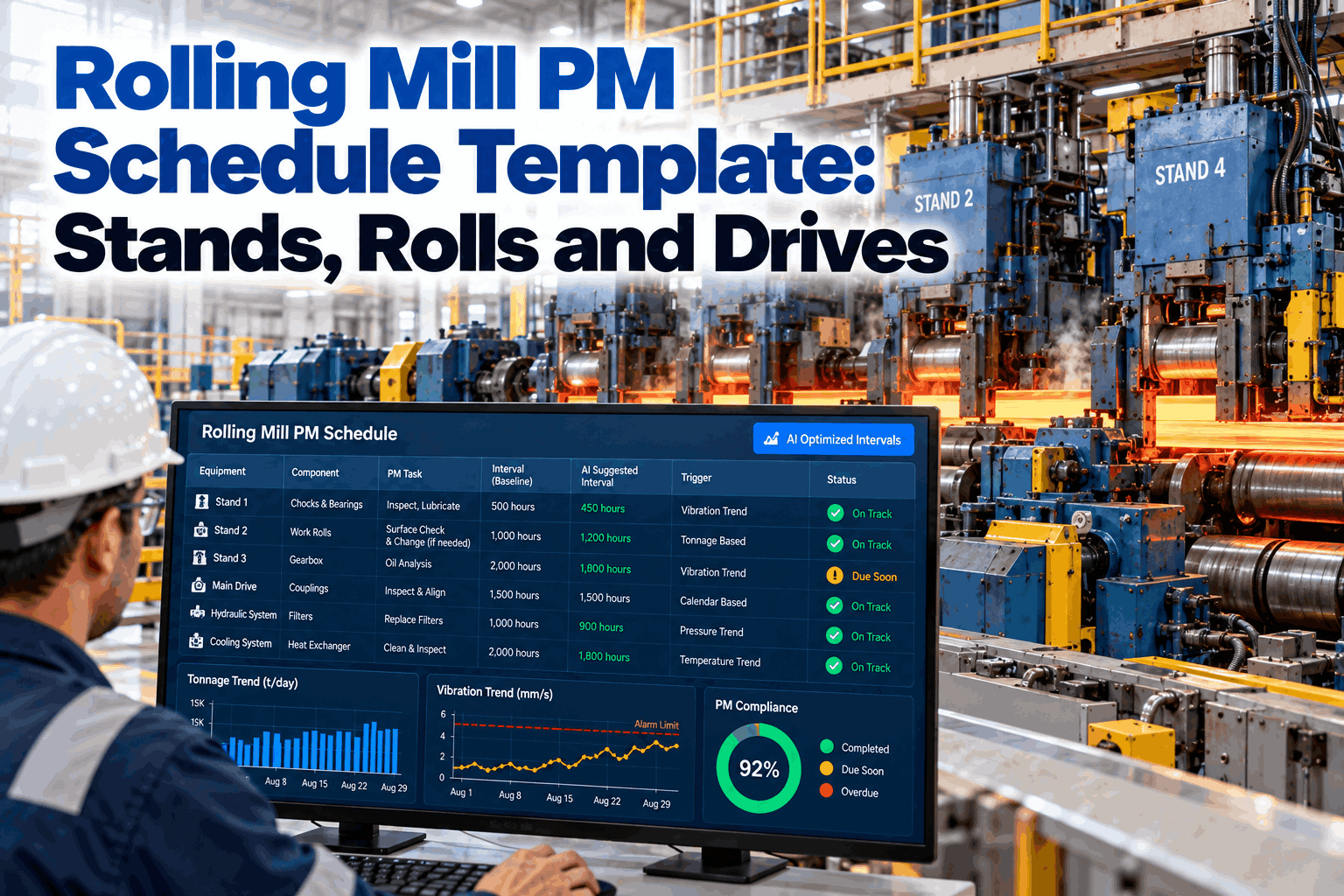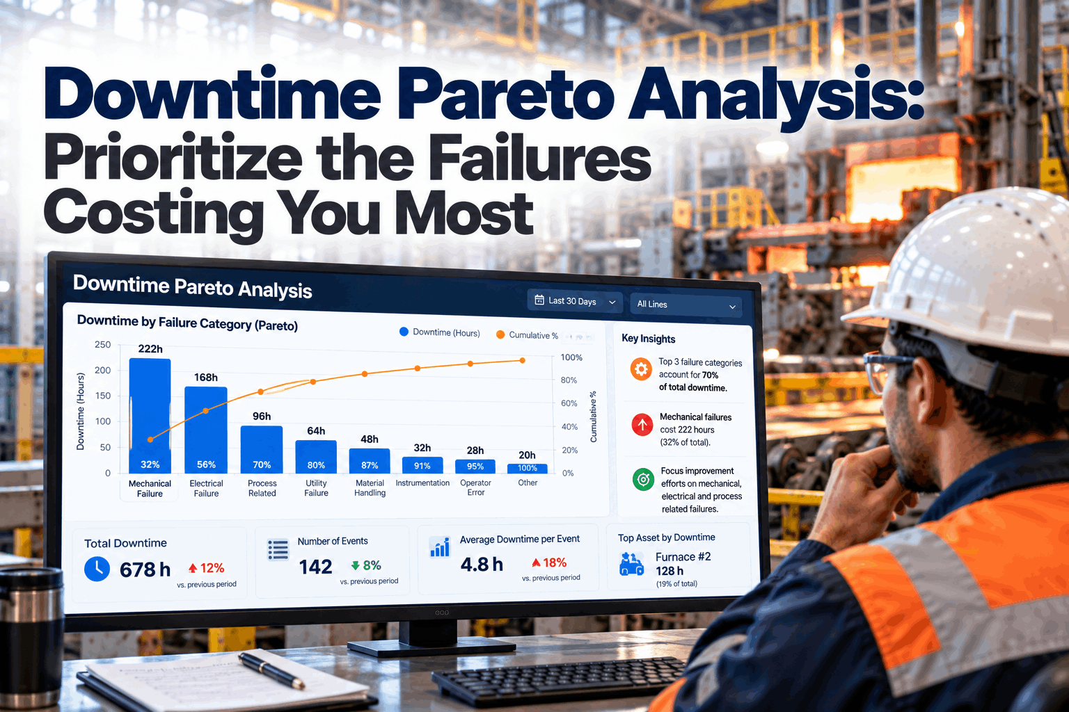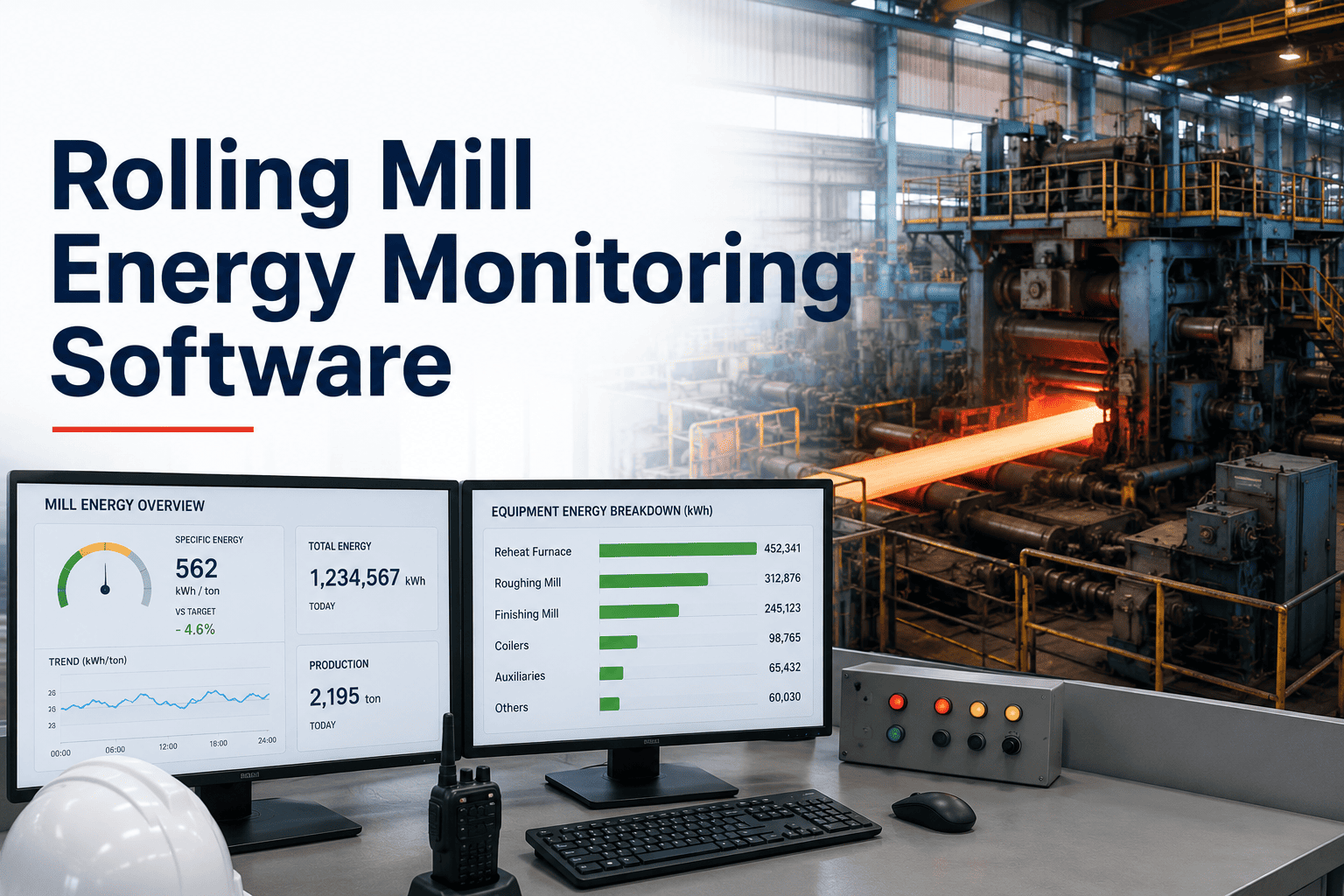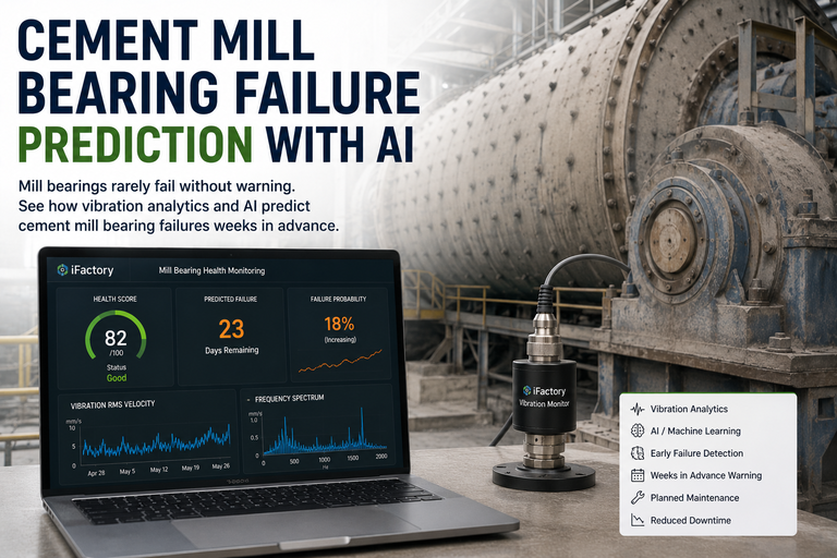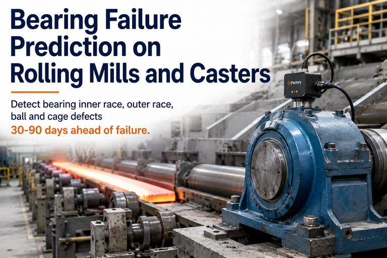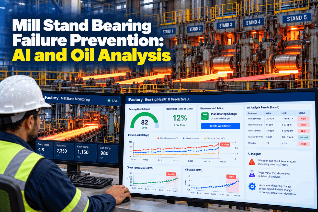
A backup roll bearing rarely fails without warning. Water creeps into the oil, one chock runs a few degrees warmer than its partner, a lab report shows tin or iron moving, and each signal sits in a different system until the bearing seizes and the stand stops for a chock change nobody planned. Mill stand bearing failure prevention brings those signals together, so the change happens at a roll change you already have on the schedule. See the combined view on real stand data in a short bearing analytics demo.
Change the Bearing at the Roll Change, Not After It Seizes
iFactory imports oil lab results automatically and combines them with chock RTD and vibration trends for every backup and work roll chock. When the risk score climbs, the bearing change is proposed for the next roll change.
Oil Film or Four-Row Tapered: Two Bearings, Two Ways to Fail
Most flat mill stands use two bearing families. Backup rolls in many hot and cold mills run in oil film bearings of the Morgoil type: a tapered steel sleeve on the roll neck turns inside a babbitt-lined bushing on a hydrodynamic film of oil, with no metal contact while the film holds. Work rolls, and the backup rolls of some mills, run in four-row tapered roller bearings (TQO), which carry radial and axial load through rollers and run on grease, oil-air or circulating oil. Each family gives different early warnings, so the monitoring has to match the bearing. Check your stand layout with our bearing specialists.
Five Failure Modes That End in an Unplanned Chock Change
ISO 15243 groups rolling bearing damage into six families, from rolling contact fatigue and wear to corrosion and fracture, and oil film bearings add a pattern of their own in babbitt wiping. In a mill stand, five mechanisms are worth tracking by name, and several of them start with water or scale reaching a place it should never get to. Knowing the first signal of each one tells you which data to watch. Go through your own teardown history in a failure mode review.
Four Temperature Patterns and What Each One Usually Means
An RTD in the chock or in the return oil is the cheapest signal you have, and a single alarm limit wastes most of it. A chock that sits well under its limit can still be in trouble if it climbs a little every day or runs hotter than the chock on the other end of the same roll. The shape of the trend, compared with that chock's own history and with the opposite side, says far more than the number alone. For grease-lubricated TQO chocks there is another reason to watch: FAG notes that grease life roughly halves with each 15 degrees above its continuous limit temperature. Map your RTD points with our support team.
Reading a Lab Report for the Bearing, Not Just the Oil
A lab report describes the oil. The planner needs to know what it says about the bearing. Water is the first line to read for an oil film system: Machinery Lubrication notes that mill oil performs best with water kept consistently below 0.5%, and that mills typically allow no more than 2% at any time. Wear metals point to which part is wearing, and particle counts show how much hard debris the film has to cope with. Use your bearing maker's limits and trend each result against the same chock group's history. See lab results matched to chocks in a lab import demo.
One Risk Score Instead of Three Separate Reports
The predictive model reads the lab result, the RTD trend and the vibration level together for each chock. Planners see the score, the reason behind it and the roll change where the swap fits.
What Vibration Can and Cannot Tell You on a Backup Roll
Vibration analysis works best on fast machines. Many backup rolls turn slowly, and low-speed bearings, often defined as running below about 100 r/min, are harder to monitor with standard vibration methods. Oil film bearings add another limit: with no rolling elements there are no bearing defect frequencies to find, so the film fails quietly until temperature moves. That does not make vibration useless, but on a backup roll it works as one input among several, not as the main alarm. Ask our reliability engineers where vibration earns its place on your stands.
- TQO work roll chocks running at normal rolling speed
- Spotting a change from the first coil after a roll change
- Looseness, spindle and gearbox faults near the stand
- Confirming a fault that oil or temperature already suggests
- Water and tin trends for oil film bearings
- Chock RTDs compared operator side to drive side
- Acoustic emission, which can pick up crack initiation and lubrication problems even at very low speeds
- Teardown findings from the chock shop, fed back as labels
Three Risk Bands, Each With a Clear Action
A risk score only helps if everyone knows what each level means on the floor. Work roll chocks come out often, so a TQO concern can usually wait for the next work roll change. Backup roll changes are further apart, so an oil film bearing near the top band may justify moving that change a little earlier. The bands below are an example; your team sets the boundaries from its own failure and teardown history. See band settings in a planning demo.
A Chock Shop Inspection Checklist for Every Teardown
The chock shop sees every bearing the sensors only hint at. FAG's rolling mill guidance recommends a thorough bearing check after 1,000 to 1,200 running hours, turning the outer rings to bring a fresh load zone into use, checking seals whenever a roll is changed and keeping an index card for each bearing with its temperatures and rolling loads. Those findings are also what teach the model which signals came before a real failure. Get a printable version from our support team.
Three Signal Combinations and the Call Each One Led To
The three cases below are illustrations only; none is a case study or a measured result. In each, two or three signals point to one cause. Walk through your own chock history in a signal review.
Put Your Own Delay Hours Into the Sum
The value comes from turning unplanned chock changes into planned ones, and the figures should come from your own delay records, not from industry averages. The worksheet works through assumed inputs with plain arithmetic, nothing more. Run it again with real delay data alongside our team.
Multiply the 10.5 hours by your own contribution per mill hour. Add secondary damage, such as a scored roll neck or a worn chock bore, only where your repair records show it.
Mill Stand Bearing Failure Prevention Implementation Guide, Delivered Turnkey
iFactory delivers Predictive AI with oil lab integration as a turnkey bundle. A pre-configured NVIDIA AI server ships racked and ready with the bearing risk models pre-loaded, reading chock RTDs and vibration from your PLCs and historian and lab files from your oil lab. You rack it, plug in power and Ethernet, and the AI is live. To scope it for your stands, request a turnkey quote.
- Pre-configured NVIDIA AI server, racked and ready
- Automatic import of oil lab results by sample ID
- Chock RTD and vibration links for every stand
- Chock and bearing register by serial and position
- Bearing risk model per chock, with reasons shown
- Change proposals timed to roll changes
- 24×7 remote monitoring of models and hardware
Chocks and bearings listed by serial, lab files and sensors connected, past teardown records loaded.
Risk model trained on your history and checked against known failures and teardown findings.
Risk bands agreed, change proposals switched on, planners and chock shop crews trained.
Mill Stand Bearing Failure Prevention Software Built Around the Chock
iFactory follows each chock and bearing through the mill, the lab and the chock shop, so every signal lands on the right serial number. Our support team can walk you through a pilot.
Mill Stand Bearing Failure Prevention for Plant Managers
Plan Every Bearing Change Into a Roll Change
Import lab results automatically, trend chock RTDs and vibration on every stand and let one risk score show which bearing comes out at the next roll change. Delivered turnkey and live in 6 to 12 weeks.