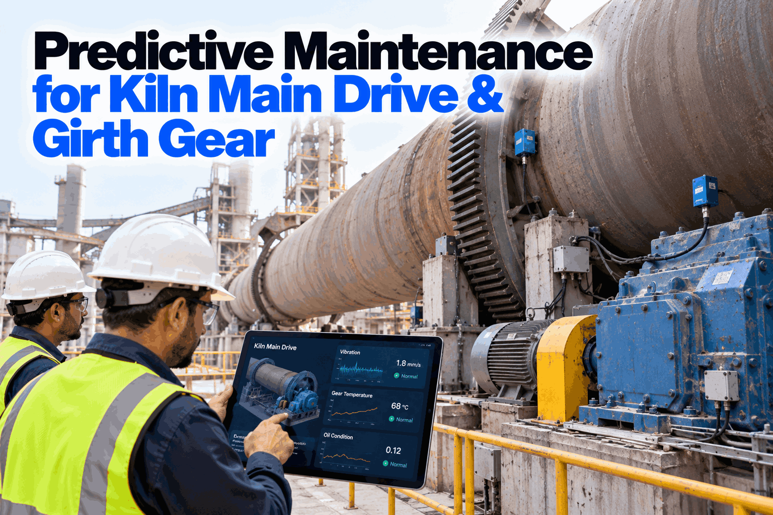
A kiln main drive rarely fails without warning. Girth gear teeth wear, the pinion slides out of alignment, gearbox oil picks up metal and motor current starts to swing with each revolution, often weeks before anything breaks. The problem is that these signals sit in different places: a thermal camera, a lab report, a vibration route and the control room trend. Predictive maintenance for the kiln main drive and girth gear brings them together, sorts process load from mechanical damage and warns while there is time to plan. Review your drive with our reliability team.
Predictive Maintenance for Kiln Main Drive and Girth Gear
Girth gear wear, pinion misalignment and main gearbox damage detected from vibration, thermography, oil analysis and motor current together, so kiln drive work is planned into a shutdown rather than forced by a failure.
- Whole drive train, motor to girth gear
- Oil analytics for the main gearbox
- Process load separated from mechanical faults
The Kiln Drive Train and Why It Fails
Four linked parts, one slow-turning load.
Most kiln main drives follow the same layout. An electric motor drives a main gearbox, which turns a pinion that meshes with the girth gear mounted on the kiln shell. Many kilns also have an auxiliary drive for slow turning during shutdowns. The whole train runs under high torque at low speed, close to heat and dust, with a shell that grows, bends and moves axially as it heats. Damage in one part spreads to the next. Monitoring one part alone misses the chain. Our reliability specialists can map your drive train.
Main motor
Variable-speed motor carrying the full kiln torque.
Main gearbox
Large reducer with bearings, gears and oil system.
Pinion
Smaller gear on its own bearings, set against the girth gear.
Girth gear
Ring gear on the shell, often on spring plates.
Failure Modes and Their Early Signals
Each fault shows up first in a different signal.
No single sensor sees every kiln drive fault. Misalignment shows up first as heat across the pinion face. Gearbox bearing and gear damage shows up in oil and vibration. Girth gear runout shows up in mesh vibration and motor current that rises and falls once per kiln revolution. Matching each failure mode to the signal that sees it earliest is the starting point for any monitoring plan. Plan your signal mix in a working session.
Why Slow Speed Makes Vibration Hard
A girth gear mesh can sit near 10 Hz, where many standard sensors struggle.
Kilns turn slowly, often a few revolutions per minute. The gear mesh frequency equals kiln speed times the number of girth gear teeth. Take a kiln at 3.5 rpm with a 180-tooth girth gear and a 22-tooth pinion. The mesh frequency is 630 cycles per minute, or 10.5 Hz, and the pinion turns at about 28.6 rpm. Signals this slow need accelerometers rated for low frequencies, long sample times and analysis tied to the actual kiln speed, which changes during operation. Without this, early gear damage is lost in noise. The figures are illustrative. Check your sensor set-up with our vibration team.
Pinion Alignment from Thermography
Heat across the pinion face shows how the load is shared.
When a pinion and girth gear are well aligned, the load spreads across the full face width and the temperature is fairly even from one end to the other. When they are not, one end carries more load and runs hotter. Guidance published by the Infrared Training Center treats a temperature difference across the face of 15 °F (about 8 °C) or less as good alignment, 15 to 30 °F (about 8 to 17 °C) as cause for concern and more than 30 °F as needing immediate investigation. Your gear supplier's own limits should take priority. Plan thermography rounds with our inspection team.
Good alignment
Load spread evenly. Keep trending.
Concern
Check alignment and lubrication soon.
Investigate now
Risk of rapid wear and profile damage.
Bands converted from the published Fahrenheit values and rounded. The same guidance notes that gear temperature within about 20 °F of ambient suggests the set has not reached operating conditions, and that lubricant film affects emissivity readings.
See Your Whole Kiln Drive on One Screen
Vibration, pinion temperatures, gearbox oil and motor current trended together, with AI separating process load from mechanical wear and flagging faults early enough to plan.
Oil Analytics for the Main Gearbox
The oil carries evidence of every gear and bearing it touches.
Oil analysis is one of the most useful tools for a kiln main gearbox, because wear particles show up in the oil before damage can be seen or heard. Results should be trended over time rather than judged against a single limit. A steady rise in iron, or a sudden jump in large particles, matters more than one high reading. Our oil analysis team can review your sampling plan.
Wear metals
Iron from gears and bearings, copper from cages and bushes.
Particle count
Reported as an ISO 4406 code and trended.
Viscosity
Change from new oil shows breakdown or mixing.
Water
Weakens the oil film and speeds wear.
Take samples from the same point, with the gearbox running and warm, at a fixed interval. Changes in method cause changes in results that look like wear but are not.
Motor Current, Torque and Process Load
Not every rise in drive power is a mechanical problem.
Kiln drive current and torque change with the process. Coating build-up, ring formation, feed rate and kiln fill all change the load on the drive. A rule that alarms on high current alone produces false alarms whenever the process shifts. Motor current signature analysis looks deeper, at patterns that repeat with each kiln or pinion revolution, which point to runout, tooth damage or rotor faults. The AI compares drive signals with process data, so load-driven changes are recognised as process and mechanical changes are raised as faults. Ask our analytics team how the models are trained.
Usually process load
- Slow rise with coating or ring growth
- Changes that follow feed rate
- Shifts after fuel or mix changes
- Even load across the revolution
Usually mechanical
- Current swinging once per kiln turn
- Patterns at pinion or mesh frequency
- Rise with no process change
- Matching change in vibration or oil
Girth Gear Runout and Shell Movement
The girth gear moves with a hot, flexing shell.
The girth gear is fixed to a shell that expands, bends and floats axially as it heats and as the kiln runs. Radial runout changes the backlash through each revolution, and axial runout or excess axial float moves the contact across the tooth. Loose or worn spring plates let the gear move relative to the shell. Measuring radial and axial runout on a schedule, and trending once-per-revolution vibration and current between checks, shows when movement is growing. Discuss your runout checks with our kiln specialists.
Radial runout
Backlash changing through each turn.
Axial runout and float
Contact moving across the tooth face.
Spring plates
Wear or looseness letting the gear shift.
How AI Turns Signals into Warning
One signal is a hint. Several moving together is a finding.
The value of combining signals is confidence. A rise in pinion temperature on its own could be a lubrication spray problem. The same rise with mesh vibration sidebands and more iron in the gearbox oil is much more likely to be real damage. The AI weighs each signal against its own history and against process conditions, ranks the likely fault and estimates how fast it is developing. Where wear develops gradually, trends can give weeks of warning, though the lead time always depends on the fault and how fast it grows. See an example in a short demo.
Kiln Main Drive Monitoring Checklist
Eight checks for a complete drive monitoring plan.
Use this checklist to review monitoring on one kiln drive first. Tick items that are already in place. Get help closing gaps from our reliability team.
Kiln Drive Monitoring Mistakes to Avoid
The costliest mistake is trusting one signal.
These are the patterns that most often let kiln drive faults reach failure. A short monitoring review can find them.
What works
- Several signal types on every drive part
- Low-frequency sensors and speed-based analysis
- Oil trended over time, same sample point
- Process data used to explain load changes
What fails
- Standard sensors on a 10 Hz mesh
- Thermography only at shutdowns
- Current alarms with no process context
- Oil results read one at a time
How iFactory Monitors the Kiln Main Drive
Predictive Maintenance and Oil Analytics, on your own network.
iFactory's Predictive Maintenance combines vibration, pinion temperatures, motor current and process data for the whole kiln drive, and Oil Analytics trends gearbox oil results from lab and online sensors. It runs on an on-prem AI server inside your plant. Fit questions go to our solutions team.
Slow-speed vibration
Analysis tied to kiln speed.
Pinion thermography
Face temperature difference trended.
Oil analytics
Wear metals, particles, viscosity, water.
Motor current
Signature analysis with process context.
Fused findings
Faults ranked across signals.
Planned work
Findings timed to the next stop.
Alarm limits, alignment and shutdown decisions remain with your maintenance team and gear supplier. Figures on this page are worked examples.
Turnkey AI: Delivered, Connected and Live in 6–12 Weeks
You do not build this. It arrives ready.
iFactory ships as a pre-configured NVIDIA AI server with the software pre-loaded, racked and ready. Rack it, plug in power and Ethernet, and the AI is live on your network. Our team handles cabling, network setup, PLC, SCADA, DCS and CMMS integration, kiln DCS and drive links, operator training and 24×7 remote monitoring. Data stays on your network. For a scope matched to your plant, request a turnkey quote.
Ship, network and data
Server installed. Drive sensors, DCS, oil lab results and motor data connected.
Model training and pilot
Speed-based vibration, thermography, oil and current models trained on your kiln drive.
Go-live and training
Kiln drive monitoring live. Reliability team trained. 24×7 monitoring begins.
Frequently Asked Questions
What are the most common kiln main drive failures?
Pinion misalignment, girth gear tooth wear and pitting, gearbox gear and bearing wear, girth gear runout and loose spring plates.
Why is vibration monitoring hard on a kiln drive?
The kiln turns slowly, so the girth gear mesh can sit near 10 Hz. It needs low-frequency sensors, long samples and analysis tied to kiln speed.
How is pinion alignment monitored?
By measuring the temperature difference across the pinion face. A growing difference shows one end carrying more load.
What should gearbox oil analysis include?
Wear metals, particle count, viscosity and water, trended over time from the same sample point.
Can motor current show mechanical faults?
Yes. Current that swings once per kiln or pinion revolution can point to runout or tooth damage, when process load is ruled out.
How does the AI avoid false alarms from coating?
It compares drive signals with process data such as feed, speed and coating indicators, so load changes are not reported as mechanical faults.
How much warning can we expect?
It depends on the fault. Gradual wear can give weeks of warning, while sudden damage gives less. The pilot measures this on your own drive.
Does it work with our existing sensors?
Yes, where they suit slow-speed work. The pilot reviews current sensors and adds low-frequency or temperature sensing where needed.
How do we start?
Start with one kiln drive. A 6-week pilot connects sensors, oil data and the DCS, and sets up models and alarms. To plan it, contact our team.
Plan Kiln Drive Work Before It Plans Itself
In thirty minutes we review your kiln drive data and show which signals are missing and which faults could be caught earlier. You keep the review either way.
- 1Drive layout and gear teeth counts
- 2Recent vibration reports
- 3Pinion thermography images
- 4A year of gearbox oil results
- 5Details of the last drive failure or repair