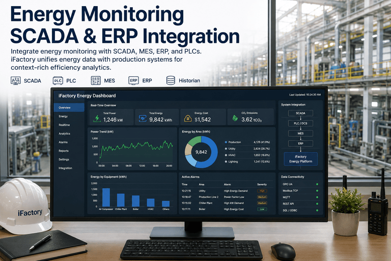
Real-time energy monitoring is only as good as the hardware feeding it — and the good news for most manufacturers is that a lot of that hardware is already in the plant. Behind every live consumption dashboard sits a physical measurement chain: current sensors clamped around conductors, voltage taps, power and energy meters that turn those signals into calibrated kilowatts, and communication gateways that carry the data up to the analytics layer. Understanding that chain matters, because the choices at each layer determine accuracy, install effort, and whether you can deploy without shutting down a line. The encouraging part is that modern sensors are built for retrofit — split-core CTs clamp around an existing cable without cutting it, wireless meters eliminate long signal runs, and multi-channel sub-meters read dozens of circuits from one panel-mounted unit. And a well-designed platform doesn't demand new hardware everywhere: it reads the meters, drives, and PLCs you already own through standard protocols, adding sensors only where a real coverage gap exists. To see what your existing hardware already supports, book a demo.
MANUFACTURING · ENERGY MONITORING HARDWARE
The Sensors, Meters, and Gateways Behind Machine-Level Energy Data.
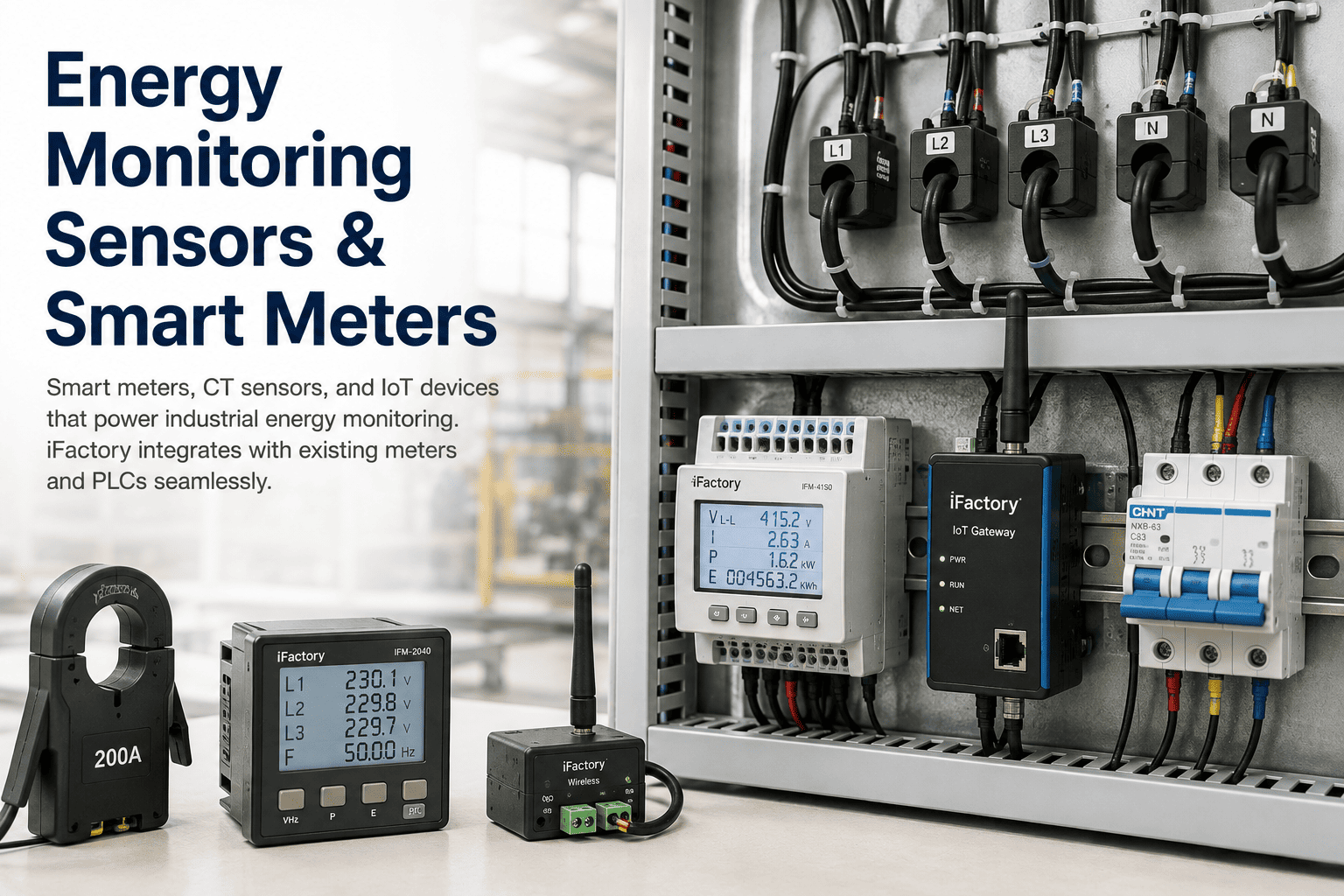
CT sensors, smart meters, and IoT devices are the measurement chain that powers industrial energy monitoring — and most of yours is retrofit-friendly or already installed. iFactory's equipment submetering integrates with existing meters, drives, and PLCs through standard protocols, adding split-core CTs and wireless sub-meters only where coverage is thin, so you reach machine-level visibility without a rip-and-replace.
3 layers
Sensors, meters, and gateways in the chain
no shutdown
Split-core CTs clamp on without cutting wires
24 circuits
Single-phase points one multi-channel sub-meter reads
0.2–0.5%
Accuracy class of revenue-grade industrial meters
The Measurement Chain, Layer by Layer
Every energy monitoring deployment is built on the same three-layer hardware stack, and knowing what each layer does makes the whole system legible — and makes it obvious which pieces you can reuse and which you might add. Data flows up the chain: sensors measure the physics, meters turn it into calibrated numbers, and gateways carry those numbers to the platform.
LAYER 1
Sensors — Measure the Physics
Current transformers clamp around conductors to measure amperage, and voltage sensors tap the supply, converting the raw electrical quantities into signals a meter can read. These transducers are the foundation — a current transformer customized for the service and power level, paired with a voltage module configured for the connection type, whether single-phase two-wire or three-phase four-wire. Everything above depends on the accuracy and correct sizing of this layer.
LAYER 2
Meters — Turn Signals Into Calibrated Numbers
Power and energy meters take the sensor signals and compute real, reactive, and apparent power, power factor, and cumulative kilowatt-hours with documented accuracy. A power meter reads real-time voltage, current, and instantaneous power; an energy meter records cumulative consumption over time — most industrial units do both, across single- and three-phase systems, and log the data internally. This is the layer that gives numbers you can bill and benchmark against.
LAYER 3
Gateways — Carry Data to the Platform
Communication gateways and edge devices collect meter data over industrial protocols, translate between them, and deliver it to the analytics platform — wired over RS485 and Ethernet or wireless over long-range low-power links. This layer normalizes a mixed estate of meters and drives into one data stream and buffers it against network interruptions, so the platform sees a unified, reliable feed regardless of what hardware sits below.
Current Sensors: The Retrofit Workhorses
Because current sensing is where most retrofit decisions are made, it's worth knowing the three main sensor types and when each fits. The defining advantage of modern current sensors is non-invasive installation — clamping around an existing conductor without cutting it or interrupting power, which is what makes monitoring a running plant practical.
01
Split-Core CTs
A split-core current transformer has a hinged or removable leg that presses open, so it installs around an existing cable without disconnecting wires or interrupting power. This non-invasive design makes it the workhorse of retrofit and semi-permanent metering, and revenue-grade split-core CTs reach the high accuracy classes required for billing-grade submetering — combining easy install with precision.
02
Solid-Core CTs
A solid-core CT is a closed ring the conductor passes through, offering stable, high-accuracy measurement for permanent installations where the circuit can be opened during fit-out. It's the choice for new panels and greenfield builds, where the conductor can be threaded through at construction and the sealed core delivers reliable long-term readings.
03
Rogowski Coils
A Rogowski coil is a flexible, rope-like sensor that wraps around irregular or large conductors and busbars in crowded panels where a rigid CT won't fit, with a very wide current range from a few amps to tens of thousands. It needs an integrator to correct its inherent phase shift, but its flexibility and range make it the answer for tight or high-current installations.
04
Voltage Sensing
Voltage is tapped directly at the panel, and newer non-invasive options snap magnetic probes onto breaker screws with no terminal wiring or wire stripping required. Combined with a current sensor's amperage and the measured power factor, voltage completes the picture needed to compute true power and energy rather than just current.
The retrofit story is the practical heart of hardware selection: split-core clamps and snap-on voltage probes mean a plant can reach machine-level metering without cutting a cable, stripping a wire, or shutting down a line. That non-invasive install is what turns energy monitoring from a shutdown project into a live-plant upgrade.
See What Your Panels Already Support
Bring your meter models, drive types, and panel layouts. iFactory engineers will map what existing hardware can already feed the platform, identify where a split-core CT or wireless sub-meter fills a gap, and show the path to machine-level visibility with the least new hardware.
Meters and Sub-Meters: Accuracy and Density
Above the sensors sit the meters, and two things matter most when choosing them: how accurately they measure, and how many circuits one unit can cover. Getting both right is what makes machine-level metering affordable at scale rather than a meter-per-machine cost explosion.
ACCURACY
Revenue-Grade, Documented Precision
Industrial power and energy meters provide calibrated measurements with documented accuracy specifications — commonly ANSI C12.20 Class 0.2 or 0.5 and IEC 62053 Class 0.2S, delivering 0.2 to 0.5 percent accuracy on power and energy. Revenue-grade accuracy is what makes a sub-meter's numbers trustworthy enough for cost allocation, tenant billing, and defensible efficiency benchmarking, rather than rough indicative readings. When the goal is attributing cost to a machine or shift, the meter's accuracy class is the number that matters.
DENSITY
Many Circuits, One Unit
Multi-channel sub-meters read many circuits from a single panel-mounted device — up to eight three-phase or twenty-four single-phase circuits per unit, with compact designs fitting existing panel boards on a DIN rail. This density drastically reduces hardware investment and network complexity: instead of a separate meter per machine, one unit covers a whole panel of loads, which is what makes granular, machine-level submetering economical across a plant rather than only on a few critical assets.
There's also existing metering to harvest before adding anything. Variable-speed drives from major vendors embed energy counters accessible over Modbus or Ethernet, and combined protection-and-metering relays log energy alongside their protective function — so many motor and feeder loads already report consumption without a single new meter, if the platform knows how to read them.
Protocols: How the Data Gets to the Platform
A meter is only useful if its data reaches the analytics layer, and that's a question of protocols. Industrial energy hardware speaks a well-established set of them, and a platform's value depends on speaking all of them — so a mixed estate of meters from different eras and vendors federates into one stream.
Modbus RTU & TCP
The workhorse of industrial metering — Modbus RTU over RS485 serial and Modbus TCP over Ethernet are supported by the vast majority of power meters and sub-meters, making Modbus the most common path for pulling energy data off the floor.
OPC-UA
The modern standard for secure, platform-independent industrial data exchange, OPC-UA is the preferred aggregation protocol for tying meters, PLCs, and SCADA into one secure, structured data layer that scales cleanly across a large plant.
BACnet, DNP3 & IEC 61850
BACnet MS/TP bridges building-management systems and HVAC metering, while DNP3 and IEC 61850 handle power-distribution and protection-relay data — the protocols that bring facility and electrical-infrastructure metering into the same view.
MQTT & REST API
MQTT carries lightweight edge and IoT sensor data efficiently to the platform, and REST APIs plus time-series historians integrate consumption with production and business systems — the layer that links energy data to units produced for true efficiency metrics.
Why not just wire sensors straight into a PLC? Because CTs rated for raw PLC I/O introduce measurement error, power calculations in ladder logic lack floating-point precision, and many PLCs don't have enough inputs for full three-phase measurement. Calibrated industrial meters with documented accuracy are the right instrument — and the platform reads their data over these protocols rather than trying to compute energy in control logic.
Wireless: Metering Without the Cable Runs
For distributed panels and hard-to-cable locations, wireless metering removes the single biggest install cost — the signal wiring. Wireless sensors clamp on and transmit, turning a rewiring job into a mounting job and making coverage of scattered loads practical.
LoRaWAN Current Sensors
A LoRaWAN current sensor uses a split-core clamp or Rogowski coil around an existing cable, samples the reading, and transmits it over a long-range, low-power link to a gateway — no long signal cables between panels, meters, and the platform. It's ideal for distributed electrical panels, branch circuits, and equipment scattered across a large facility, cutting wiring work, install time, and retrofit cost dramatically.
Non-Invasive, Fast to Scale
Because both the current clamp and the newer snap-on magnetic voltage probes install without cutting cables or interrupting power, a wireless sub-meter deploys in minutes per point and scales across a plant without a wiring project. Mixing split-core CTs and Rogowski coils on one wireless host lets different current ranges share a single unit, so a diverse panel is covered without matching specialized hardware to every circuit.
How iFactory Integrates With What You Have
The platform is deliberately hardware-agnostic: its job is to read energy data from whatever measurement hardware is present and add to it only where needed. That's what makes equipment submetering a fast, low-disruption upgrade rather than a capital re-instrumentation.
1
Read Existing Meters, Drives, and PLCs
The platform connects to the meters, sub-meters, VSD energy counters, protection relays, and PLC data you already have through Modbus, OPC-UA, BACnet, MQTT, and REST — harvesting consumption from hardware already in the plant before any new device is considered.
2
Add Sensors Only Where Coverage Is Thin
Where a critical machine or line has no metering, split-core CTs, Rogowski coils, or multi-channel wireless sub-meters are added non-invasively — clamping on without a shutdown — so a gap is filled at the specific asset rather than re-metering the whole plant.
3
Normalize to Machine-Level kWh Per Unit
Data from every source is unified and normalized to energy per machine and per unit produced, so a mixed estate of meters becomes one consistent, comparable view — the machine-level resolution that turns raw consumption into an attributable, actionable metric.
4
Feed the Analytics and Work-Order Loop
The unified hardware feed drives the platform's anomaly detection and ties an energy waste directly to the equipment causing it, generating a maintenance work order — so the measurement chain doesn't just display data but triggers the fix that captures the saving.
Choosing the Right Hardware for the Job
There's no single right sensor or meter — the right choice depends on whether you're retrofitting or building new, how much accuracy the use demands, and how the loads are laid out. A few practical guidelines cover most decisions.
Retrofit a Running Line
Reach for split-core CTs and snap-on voltage probes, wired to a multi-channel sub-meter or a wireless LoRaWAN host — non-invasive install with no shutdown. Rogowski coils handle the crowded panels and large busbars where a rigid CT won't fit, keeping even tight or high-current retrofits practical.
Instrument a New Panel
Solid-core CTs threaded at build time give the most stable long-term accuracy, paired with a DIN-rail multi-circuit meter sized for the panel's channel count. Building metering in during construction is cheaper and cleaner than retrofitting it later, so new panels should be specified with monitoring in mind.
Bill or Allocate Cost
When numbers must support cost allocation or billing, specify revenue-grade meters and CTs at ANSI Class 0.2/0.5 or the equivalent IEC class, so the accuracy is defensible. For rough waste-finding, lower classes suffice — match the accuracy class to whether the data needs to hold up financially.
Cover Distributed Loads
For scattered panels and remote equipment, wireless LoRaWAN sensors avoid expensive cable runs and deploy fast, while multi-channel sub-meters keep the device count and network complexity down where loads cluster on shared panels. Match the topology to how the loads are actually distributed across the plant.
What This Means for Deployment
Understanding the hardware layer changes what an energy-monitoring project actually involves — usually far less new equipment, disruption, and cost than plant teams expect.
01
Most Hardware Is Already There
Existing meters, VSD energy counters, protection relays, and PLC data already report consumption for much of the plant, so the platform harvests them first and new sensors fill only genuine gaps — sharply cutting the hardware bill versus a full re-metering.
02
No Shutdown to Install
Split-core CTs and snap-on voltage probes clamp onto live conductors without cutting cables or interrupting power, so metering a running line is a mounting task, not a production outage — removing the biggest objection to instrumenting a busy plant.
03
Machine-Level Without Meter-Per-Machine
Multi-channel sub-meters covering up to two dozen circuits from one unit make granular submetering affordable, so machine-level resolution doesn't require a separate meter on every asset — the density that makes plant-wide visibility economical.
04
One Platform, Any Vendor
Because the platform speaks every common protocol and is hardware-agnostic, a mixed estate of meters, drives, and sensors from different vendors and eras federates into one consistent view — no need to standardize on a single hardware line to get unified data.
Frequently Asked Questions
The questions plant and facility engineers ask most often about energy monitoring hardware.
Do we need to shut down to install energy sensors?
In almost all cases, no. Modern current sensors are designed for non-invasive installation: a split-core CT has a hinged or removable leg that presses open and clamps around an existing cable without disconnecting wires or interrupting power, and Rogowski coils wrap flexibly around conductors and busbars the same way. Voltage sensing has followed — newer non-invasive options snap magnetic probes onto breaker screws with no terminal wiring or wire stripping. This means metering a running line is a mounting task rather than a shutdown, which is exactly what makes energy monitoring practical to retrofit into a busy plant. Solid-core CTs, which require threading the conductor through a closed ring, are reserved for new panels where the circuit is open during construction. For a running facility, the split-core and clamp-on approach lets you reach machine-level metering without a production outage. To plan a no-shutdown rollout,
book a demo.
Can iFactory use the meters and drives we already have?
Yes — that's the core of the approach. The platform is hardware-agnostic and reads energy data from whatever measurement hardware is already present through standard industrial protocols like Modbus RTU and TCP, OPC-UA, BACnet, MQTT, and REST. That includes dedicated power and energy meters, but also energy counters embedded in variable-speed drives from major vendors, combined protection-and-metering relays that log energy alongside their protective function, and consumption data available through your PLCs. Many motor and feeder loads therefore already report consumption without a single new meter — the platform just needs to know how to read them. New sensors are added only where a critical asset genuinely has no metering, so the project harvests existing hardware first and fills gaps second. This is what keeps an energy-monitoring deployment fast and low-cost: you're reusing the substantial measurement infrastructure already in the plant rather than replacing it.
What's the difference between a CT, a power meter, and an energy meter?
They're three links in the measurement chain. A current transformer, or CT, is a sensor — it clamps around a conductor and converts the current flowing through it into a small signal a meter can read, but on its own it doesn't compute anything. A power meter takes the CT's current signal plus a voltage input and calculates real-time electrical parameters: voltage, current, power factor, and instantaneous power in kilowatts. An energy meter records cumulative consumption over time, typically in kilowatt-hours, giving you the total energy used across a period. In practice most industrial meters do both power and energy, across single- and three-phase systems, and log the data internally. So the CT measures the physics, and the meter turns that measurement into the calibrated real-time and cumulative numbers you actually manage against. Choosing the CT sets your install method and accuracy at the sensor level; choosing the meter sets your accuracy class, channel density, and communication protocol.
How accurate do the meters need to be?
It depends on what the data has to support. Industrial power and energy meters carry documented accuracy specifications, commonly ANSI C12.20 Class 0.2 or 0.5 and IEC 62053 Class 0.2S, which translate to roughly 0.2 to 0.5 percent accuracy on power and energy. If you need the numbers to support cost allocation, tenant billing, or defensible efficiency benchmarking, specify revenue-grade meters and CTs at these classes so the data holds up financially. If the goal is simply finding waste — spotting a leak, a phantom load, or a drifting machine — lower accuracy classes are perfectly adequate, since you're looking at relative change and trends rather than billing-precise absolutes. The practical guidance is to match the accuracy class to the use: pay for revenue-grade precision where money changes hands based on the reading, and use standard-grade hardware where you just need reliable trend visibility. Over-specifying accuracy everywhere adds cost without adding value.
Should we just wire current sensors into our PLC?
Generally no, for a few concrete technical reasons. CTs and voltage sensors rated for raw PLC I/O introduce measurement error, power calculations performed in ladder logic lack the floating-point precision that accurate energy computation needs, and many PLCs simply don't have enough sensor inputs to handle full three-phase measurement across multiple circuits. Calibrated industrial power meters exist precisely to solve this — they provide documented, revenue-grade accuracy that a PLC-based calculation can't match. The better architecture is to let dedicated meters do the measurement and let the platform read their data over standard protocols like Modbus or OPC-UA, rather than trying to compute energy inside control logic. That said, the platform does read genuine energy data your PLCs already carry, and it reads the energy counters embedded in variable-speed drives and protection relays — so PLC and drive data absolutely feed the system, they're just not asked to perform metering-grade calculations they weren't designed for. Contact
iFactory support to review your specific hardware.
REUSE WHAT YOU HAVE · ADD ONLY WHAT YOU NEED
Machine-Level Energy Data From the Hardware You Already Own — Plus a Few Clamp-On Sensors.
CT sensors, smart meters, and IoT devices are the measurement chain — and iFactory's equipment submetering reads your existing meters, drives, and PLCs over Modbus, OPC-UA, and MQTT, adding split-core CTs and wireless sub-meters only where coverage is thin. Non-invasive install with no shutdown, revenue-grade accuracy where it matters, and one hardware-agnostic view across every vendor and protocol.