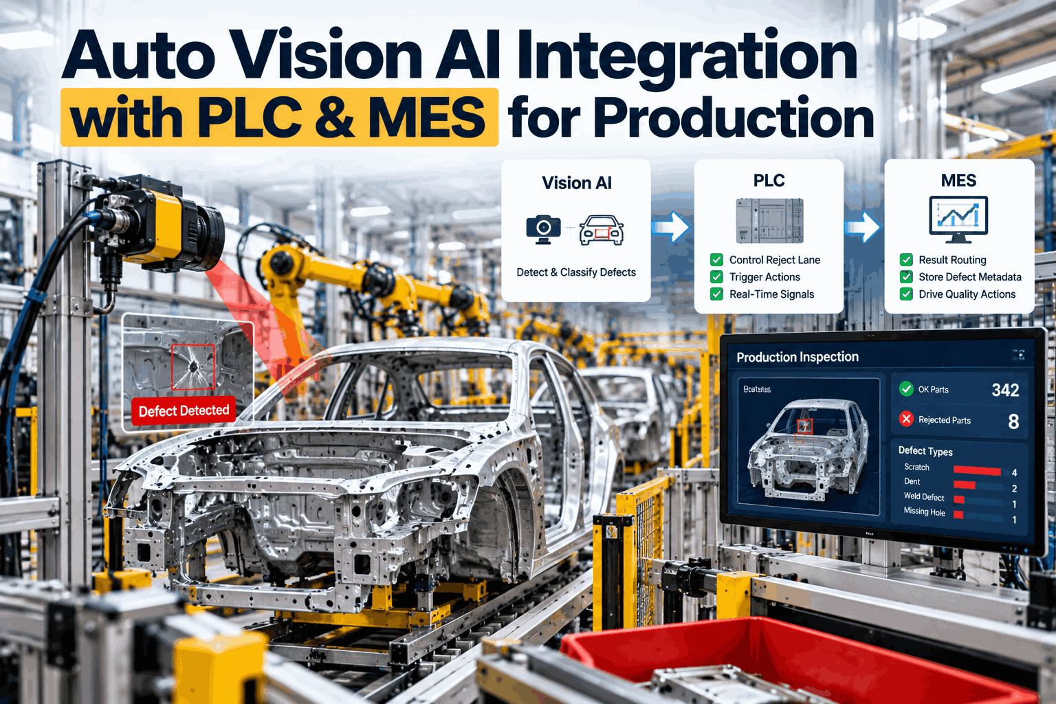
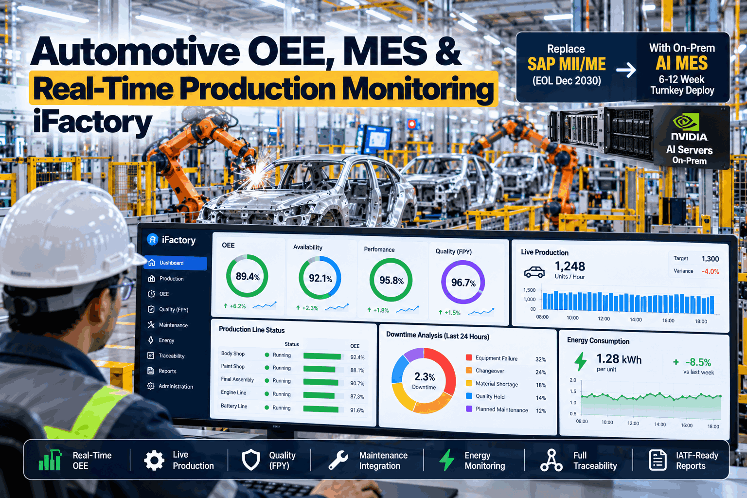
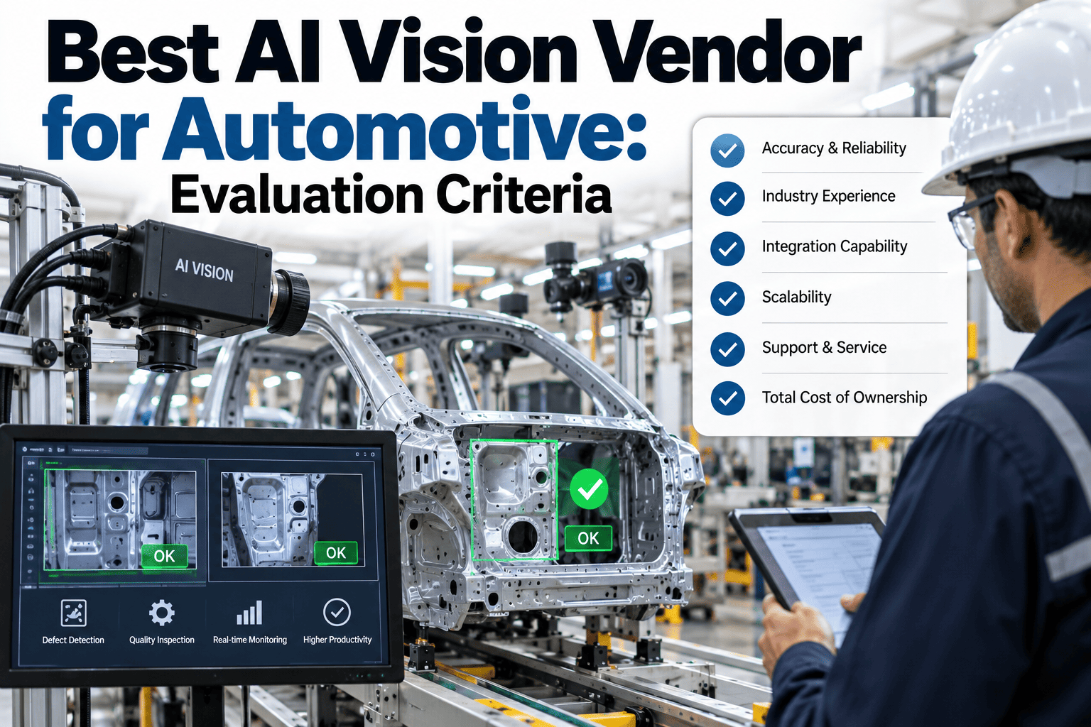
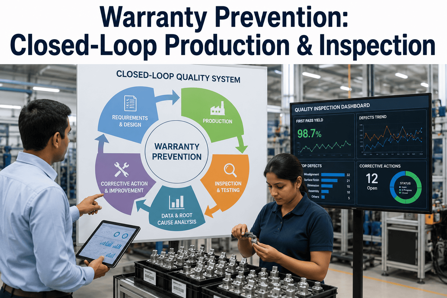
Most automotive plants that have bought vision inspection already know it can find defects. The harder question is what happens in the half second after it does. If the result stays on the vision station's own screen, an operator has to notice it, a conveyor keeps moving, and the body or part travels on to the next process with a defect that has already been seen. If the result reaches the PLC but not the MES, the part is diverted correctly and then disappears: no defect record, no link to the VIN or body ID, no disposition, no trend. Integration is what turns a detection into a decision, and the decision into a quality record and a corrective action. It works in two layers that must agree with each other. The PLC handles what has to happen in real time: pass, reject, divert, hold, or stop. The MES handles what has to be remembered and acted on: the defect type and location, the image evidence, the rework route, and the pattern across shifts. Getting both right requires a clear interface design, a fail-safe policy, and a metadata model that survives model updates. This guide covers the architecture, the result routing logic, the defect metadata handoff, and a practical rollout, with an integration readiness checklist at the end. iFactory Automotive Vision AI and Quality Inspection is built to connect vision results to the line and the quality system, live.
iFactory Vision AI - Automotive Quality Inspection
Auto Vision AI Integration with PLC and MES for Production
Real-time result routing, reject-lane control, and defect metadata handoff that turn every vision inspection into a line decision and a traceable quality record.
Real time
result delivered to the PLC within the station cycle
100%
of results linked to a VIN or body ID in the MES
Fail-safe
defined default behaviour on camera or network fault
Closed loop
from defect detection to corrective action
Where Vision Results Get Stuck
Plants often describe their vision inspection as integrated when it is only partly connected. These four stages show how far a result actually travels after the camera makes its call.
Stage 1
Stand-alone station
The vision system shows pass or fail on its own screen. An operator reads it, decides what to do, and writes it down if anyone asks. Nothing is connected to the line.
Recognition signal: "The camera flagged it, but it had already gone to the next station."
Stage 2
Hardwired pass or fail
A discrete output tells the PLC to reject. Stopping the defect works, but the PLC knows only that something failed, not what, where, or on which vehicle.
Recognition signal: "We know the reject count" - but not which defects make it up.
Stage 3
PLC integrated with data
Result, defect class, and body ID pass to the PLC over a network handshake. Routing is accurate and the line state is known, but the quality system still depends on manual entry.
Recognition signal: "Quality re-keys the defect later" - with the image attached by hand.
Stage 4
Closed loop with MES
The PLC acts in real time while the MES receives the full defect record, assigns disposition, and feeds trends back to the process owner and the model.
Recognition signal: "The repeat defect raised its own work order" - before the shift ended.
The Integration Architecture - Four Layers, Each With One Job
A reliable integration gives each layer a single responsibility. The layers below separate the real-time decision from the system of record, so a slow database or a network pause never delays a diverter.
Layer 1
Vision AI and Edge Inference
Cameras, lighting, and the edge compute node that runs the model at the station. The edge node produces the result, confidence, and defect details, and holds a local buffer if upstream systems are unavailable.
Inference at the station
Decision made locally so the result is ready within the station cycle time
Local result buffer
Results and images stored at the edge and forwarded when the network returns
↓
Layer 2
PLC and Line Control
The PLC owns every physical action: diverter, gate, stop, or hold. It receives a compact result and replies with a handshake, so the vision system knows the action was taken.
Handshake and heartbeat
Result, acknowledgement, and a heartbeat signal so a silent camera is detected, not assumed good
Reject lane and gate logic
Part tracking through the conveyor so the right body reaches the right lane
↓
Layer 3
MES and Quality Records
The MES stores the inspection against the vehicle or part, assigns disposition, and routes rework. This layer is allowed to be a moment behind, but it must never lose a result.
Genealogy and defect record
Defect class, zone, image reference, and station tied to the VIN or body ID
Disposition and rework routing
Accept, rework, scrap, or re-inspect, with the next station assigned automatically
↓
Layer 4
Analytics and Corrective Action
Where individual defects become patterns. Trends by defect class, zone, shift, and process source drive alerts, work orders, and model improvement.
Repeat defect detection
Alerts when a defect class rises against its own baseline, with the likely source
Quality action and feedback
Work orders raised and reviewer corrections returned to retrain the model
Result Routing - What the PLC Does and What the MES Does
Every inspection outcome needs two responses: one that happens in real time on the line and one that happens in the record. Defining both for every outcome, including the awkward ones, is the core of the interface specification.
Inspection outcome
PLC action
MES action
Timing
Pass
Release to next station
Store result against VIN with model version
Real time
Fail - confirmed defect
Divert to reject or rework lane
Create defect record, assign disposition and rework route
Real time
Uncertain - low confidence
Hold or route to manual review gate
Open review task with image; record reviewer decision
Real time
Vision fault or lost heartbeat
Apply fail-safe policy: hold, or divert to manual inspection
Log the outage window and list affected IDs for re-inspection
Real time
Repeat defect above threshold
Raise line warning or stop request per policy
Alert process owner and raise a corrective work order
Near real time
Recipe or model change
Confirm new model code for the variant
Record model version against every inspection
Near real time
Shift and defect trend report
No action required
Aggregate by defect class, zone, and shift for review
Batch
Defect Metadata Handoff - What Travels With Every Result
A pass or fail flag is enough to move a part. It is not enough to fix a process. The metadata below should travel with every inspection, so quality, rework, and engineering teams can act without going back to the station.
Identity
VIN, body ID, or part serial
Station and camera identifier
Timestamp synchronised to plant time
Model variant and recipe code
Shift and line
Defect
Defect class and severity
Location or zone on the part
Size or area measurement
Model confidence score
Count of defects on the part
Evidence
Image reference and annotated overlay
AI model name and version
Lighting and exposure settings
Calibration status at time of capture
Retention period for the image
Disposition
PLC action taken and lane used
Reviewer decision and time
Rework route and next station
Final outcome: accept, rework, scrap
Reviewer feedback for retraining
The Integrated View - Station, Lane, Record, and Alert
When the integration works, a single event can be followed from the camera to the PLC, into the quality record, and out to a corrective action. This is what that chain looks like for a paint inspection station.
Vision Station VS-12
Paint final inspection
Healthy
Inspected today1,284bodies
Results delivered100%to PLC and MES
Model versionv3.2recorded per result
Result latency38 mscamera to PLC
PLC Reject Lane R2
Diverter and rework gate
6 diverted
Last hour6 rejectsabove hourly average
HandshakeConfirmedevery diversion acknowledged
HeartbeatActiveno missed cycles
Fault policyHoldon lost vision signal
MES Quality Record
Body B-77412
Recorded
DefectDirt inclusionroof, left side
DispositionReworkspot repair station
EvidenceAttachedimage and overlay
GenealogyLinkedbooth, shift, and recipe
Closed-Loop Alert
Repeat defect trend
Action
TrendDirt x3above baseline in 2 hours
Likely sourceBooth 2zone 3 air supply
NotifiedSupervisorpaint shop, on shift
Work orderRaisedfilter and airflow check
The 90-Day Integration Roadmap
Integration projects slip when the interface is agreed informally, the fail-safe case is left until commissioning, or the first live results go straight to production control. This sequence builds the specification first and proves it in shadow mode before the PLC acts on it.
Phase 1
Specification - Days 1 to 30
Week 1 to 2
Station and signal inventory
List each inspection station, its PLC, its conveyor tracking method, and the MES transaction that should receive its result. Choose the pilot stations by defect cost and by interface simplicity.
Week 3 to 4
Interface and fail-safe specification
Document the handshake, signal list, metadata fields, and the fail-safe policy for each fault case. Agree it with controls, quality, and IT before any build starts.
Phase 2
Build and Shadow - Days 31 to 60
Week 5 to 6
PLC and MES connection
Map tags, build the handshake and heartbeat, and connect the MES transaction. Test each outcome from the routing table on the bench with simulated results.
Week 7 to 8
Shadow mode on the live line
Run the vision results alongside the existing process without acting on them. Compare what the PLC would have done with what happened, and fix mismatches.
Phase 3
Live Control - Days 61 to 90
Week 9 to 10
Cutover and fault testing
Enable PLC action on the pilot station. Test the fail-safe cases deliberately, including a disconnected camera and a network pause, and record the outcome.
Week 11 to 12
Closed loop and expansion
Switch on repeat-defect alerts and work order creation. Review results, then extend to the next stations using the proven interface.
Integration Readiness Checklist
Use this checklist before a station goes live. Every item should have a named owner and an evidence record. Tick each one as it is confirmed.
Want to see your own inspection stations mapped to PLC actions and MES records? Book a demo - bring your station list, your PLC and MES details, and your top five escaped-defect cases, and we will draft the routing table and interface specification in the first session.
What Integrated Vision Inspection Delivers
These are the outcomes a plant should measure once vision results drive the line and the quality record together.
100%
Traceable inspections
each result linked to a VIN or body ID, model version, and image
Seconds
From defect to action
not the end of the shift or the next audit
Fewer
Defect escapes
because a detected defect cannot move on unrecorded
No
Manual re-keying
defect type, location, and evidence arrive in the record
Frequently Asked Questions
Our vision system already has a reject output. Why do we need a PLC and MES integration?
A hardwired reject output is a good way to stop a defect, and it should stay as a fast, reliable path. What it cannot do is tell anyone which defect it was, where it was on the vehicle, whether the part was reworked, or whether the same defect is rising. The integration keeps the real-time action in the PLC and adds the full record in the MES, so the same event serves both the line and quality.
Which protocols and systems does the integration use?
That depends on your PLC platform and MES. Typical choices are industrial Ethernet protocols such as PROFINET or EtherNet/IP for the PLC handshake, and OPC UA, REST, or a message broker for the MES. The first step is an interface review of what each system supports and what your plant standard allows. The interface is documented and versioned so it can be maintained by your own controls and IT teams.
What happens when the camera, the edge node, or the network fails?
The behaviour is decided in advance and tested. A heartbeat tells the PLC when the vision system stops responding, and the PLC then applies the agreed policy, such as holding the part or routing it to manual inspection, rather than assuming a pass. The edge node buffers results locally during a network pause and sends them on afterwards. The MES logs the outage window, so the affected vehicles can be re-inspected.
Does the vision AI become part of the machine safety system?
No. Vision inspection decides quality disposition, not personnel or machine safety. Safety functions stay on safety-rated hardware and logic, and are designed and validated separately under the applicable standards. The vision integration sits alongside them, and a vision fault must never remove or override a safety function.
How do we update the AI model without breaking the PLC and MES interface?
By keeping the interface stable and the model version visible. The signal list and metadata fields stay the same across updates, and the model name and version are recorded on every inspection. A new model first runs in shadow mode against the live line, and its results are compared with the active model before it is switched on. If results are not as expected, the previous version can be restored without touching the PLC or MES.
Make every detection count.
See iFactory Vision AI Connected to Your PLC and MES
Bring your inspection station list, your PLC and MES details, and the five defects that escaped furthest in the last year. We will map each outcome to a PLC action and an MES record, define the fail-safe behaviour, and plan a shadow-mode pilot before any control logic changes.
Real time
PLC result routing
Shadow
proven before cutover
90-day
pilot to live control