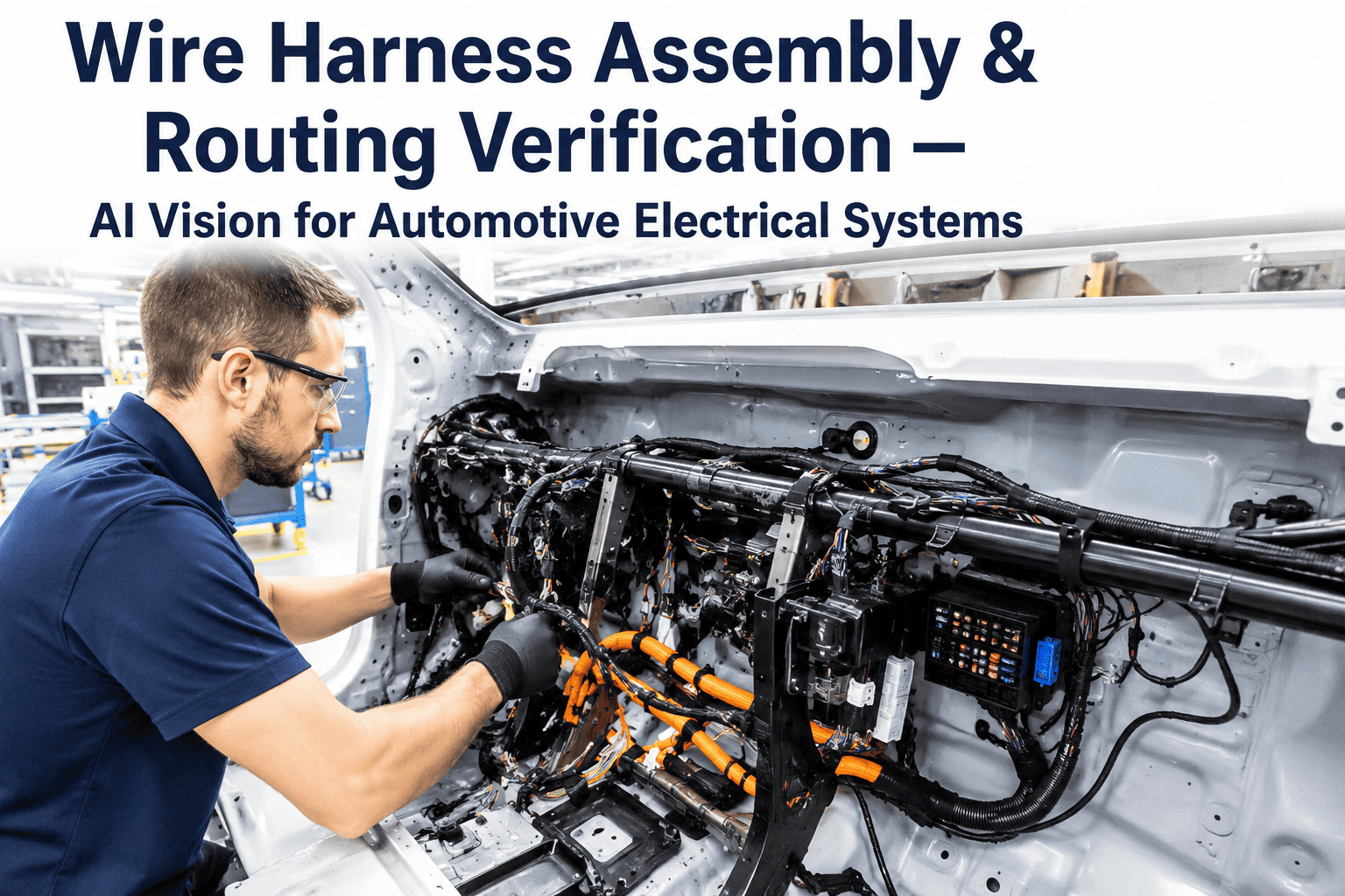
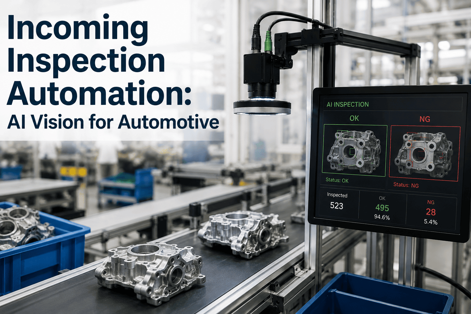
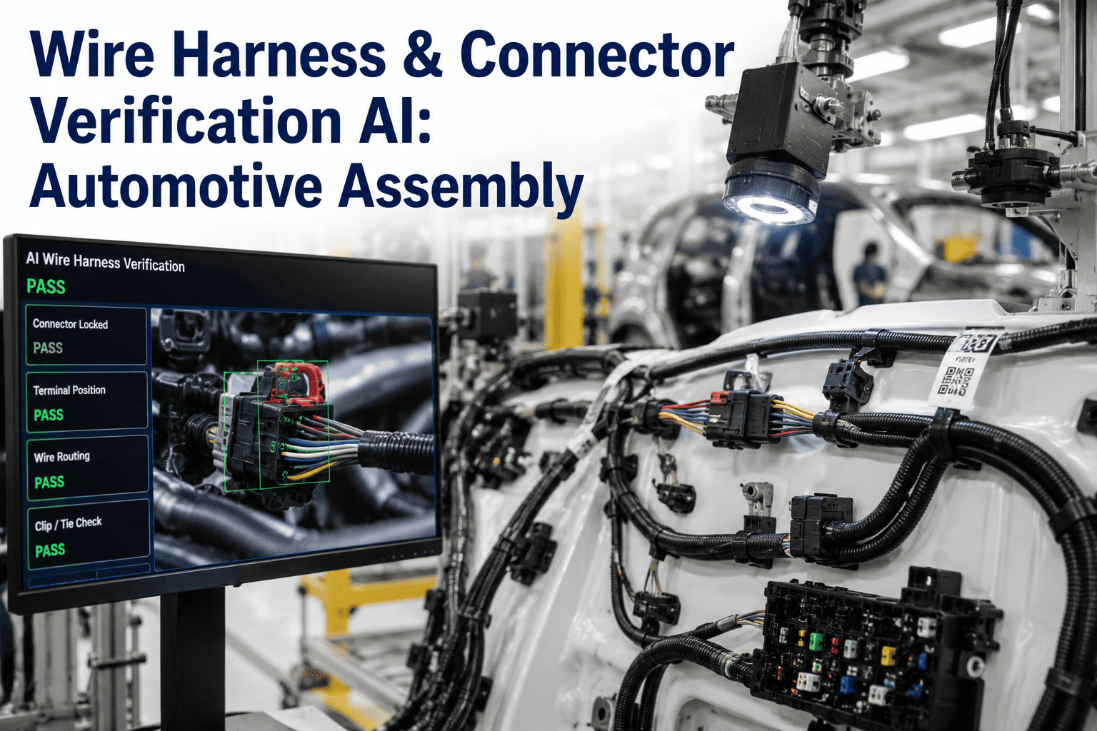
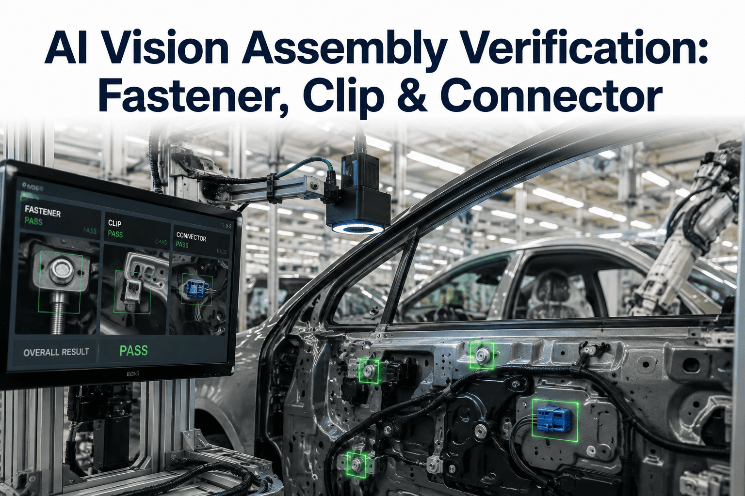
A modern vehicle harness routes hundreds of individual wires through clips, grommets, and connectors across a body that was never designed with straight lines in mind, and a single missed clip or reversed connector can sit invisible until a warranty claim traces an intermittent electrical fault months later. Human visual inspection catches the obvious misses but struggles with the subtle ones, a connector that looks seated but is not fully locked, a wire routed one clip off from its intended path, a color sequence that is almost right. AI vision systems trained specifically on harness assembly patterns catch exactly these near-misses at the station where they happen, before a partially built vehicle moves on to the next stage, which is why assembly and quality engineers are increasingly requesting a station-level vision demo on their own harness routing.
AI VISION FOR WIRE HARNESS ASSEMBLY VERIFICATION
Catch Harness Routing Errors Before They Leave the Station
Verify connector seating, clip engagement, and routing accuracy in real time across complex vehicle electrical architectures with a single camera per station.
Four Defect Categories AI Vision Is Trained to Catch
Each defect type has a distinct visual signature, and the model is trained separately against each one rather than relying on a single generic anomaly detector.
Connector Seating
Missing or Partially Seated Connectors
Camera verification confirms full connector engagement and locking tab position, catching a partial seat that would otherwise cause an intermittent field failure.
Routing Path
Misplaced Wire Ties and Grommets
Vision models compare the actual routing path against the approved reference layout, flagging a wire tie or grommet placed one clip off from its intended location.
Color and Order
Incorrect Pin Color Sequence
Multi-pin connector color sequences are checked against the approved wiring diagram, catching a sequencing error before the harness moves to electrical test.
Clip and Fastener
Unseated Clips and Loose Fasteners
Clip presence and full seating are verified immediately after installation, flagging a loose or missing clip at the exact station where it can still be corrected.
Manual Visual Check vs AI Vision at the Station
| Inspection Method |
Consistency |
Speed |
Detection of Subtle Defects |
| Manual Visual Check |
Varies with fatigue and shift |
Adds seconds per unit |
Limited for near-miss defects |
| Fixed-Rule Machine Vision |
Consistent, brittle to variants |
Fast on trained variants |
Struggles with new configurations |
| AI Deep Learning Vision |
Consistent across shifts |
Sub-second classification |
Trained on near-miss patterns |
See Station-Level Detection on Your Harness Configurations
Bring a sample of your current harness variants and see how the model performs against your specific routing patterns.
How a Flagged Defect Reaches the Operator
Step 1
Image Capture at the Station
A camera positioned at the harness installation station captures each completed routing and connector engagement immediately after the operator finishes the task.
Step 2
Classification Against Reference
The image is classified against the approved reference layout for that specific vehicle configuration, checking routing, clip position, and connector seating together.
Step 3
Immediate Station-Side Alert
A flagged defect triggers a station-side alert showing the exact location and type of issue, letting the operator correct it before the vehicle advances.
Step 4
Defect Data Logged by Station
Every flagged defect is logged against the station and shift, building a pattern view that highlights recurring issues worth a process change.
Frequently Asked Questions
Does this replace electrical continuity testing later in the process?
No, electrical continuity and high-voltage testing remain essential for validating circuit integrity and are not something a vision system can confirm on its own. Vision inspection complements electrical testing by catching physical and assembly defects, such as a misrouted wire or an unseated connector, that may still pass a basic continuity check today but create a reliability risk down the road. Teams can review how both layers work together during a
demo walkthrough.
How does the system handle the model mix complexity of different harness variants?
Each vehicle configuration has its own approved reference layout, and the vision model is trained to recognize which variant is being assembled at the station so the routing and connector checks are compared against the correct reference automatically. This avoids the common failure mode of a fixed-rule vision system flagging a correctly built variant simply because it differs from a single hardcoded reference image.
What lighting or camera setup is required at each harness station?
A single camera with appropriate lighting positioned to capture the harness installation area is typically sufficient per station, since the deep learning models are trained to handle normal variation in ambient factory lighting rather than requiring a fully controlled lighting booth. Specific station layout and camera positioning questions are best reviewed through
support based on your existing line configuration.
Can defect data from this system be traced back to a specific supplier batch of connectors or wire?
Yes, when defect patterns are logged by station and shift, that data can be correlated against incoming material batch records to identify whether a recurring connector or wire defect traces back to a specific supplier lot rather than an assembly process issue. This distinction matters because the corrective action differs significantly depending on whether the root cause sits with the operator, the fixture, or the incoming component.
How long does it take to train the vision model on a new harness variant?
Training time depends on the complexity of the variant and how much sample data is available, but the process is designed to work from a reasonably small set of approved reference images rather than requiring thousands of manually labeled examples before deployment. New variants introduced during a model changeover can typically be added to the system's reference set as part of the standard launch process rather than as a separate multi-week project.
STOP LETTING NEAR-MISS DEFECTS REACH THE FIELD
Bring Vision Verification to Your Harness Stations
Get a station-level deployment plan built around your specific harness routing and connector configurations.