Factory Layout Optimization: Digital Twin 3D Simulation

By James Smith on September 9, 2026

factory-layout-optimization-digital-twin-3d-simulation

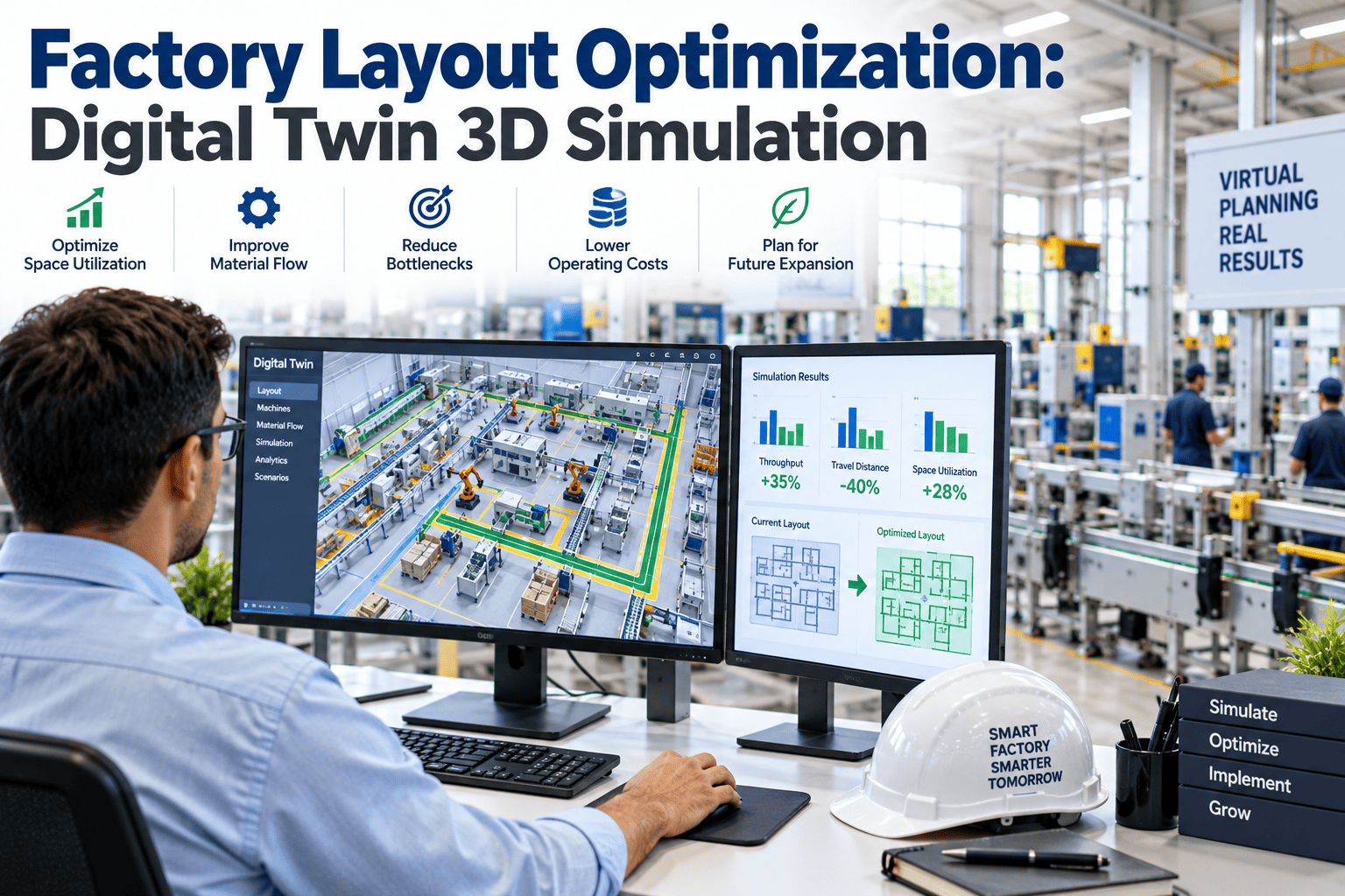
Moving a stamping press six feet to improve material flow sounds like a simple decision until the actual rigging, foundation work, and utility relocation is underway and someone realizes the new position puts the press arm within striking distance of an overhead crane's swing path. Physical layout changes in an automotive plant are expensive and disruptive to reverse, which is exactly why so many plants live with a suboptimal layout for years rather than risk a change that might create a worse problem than the one it solved. This risk aversion is entirely rational given the stakes involved, but it also means genuinely valuable layout improvements often go unrealized simply because nobody has a reliable way to test the idea before committing real capital and downtime to it. A 3D digital twin of the factory floor lets engineers test a layout change before a single bolt is loosened, simulating material flow, robot reach envelopes, and ergonomic impact in a virtual environment where a mistake costs nothing but simulation time. If you are weighing a layout change and want to see it modeled first, you can book a demo with iFactory's team.

DIGITAL TWIN · FACTORY LAYOUT · 3D SIMULATION

Test a Layout Change in a Virtual Plant Before Moving a Single Machine

iFactory's 3D digital twin simulates material flow, robot reach, and ergonomic impact for proposed layout changes, catching problems before they become an expensive physical mistake.

WHAT GETS SIMULATED

Three Dimensions of Layout Impact a 3D Twin Actually Tests

A layout change affects more than the square footage on a floor plan drawing. The simulation models the practical, physical consequences of a proposed change across the areas most likely to reveal a problem before it becomes a costly surprise. These three dimensions interact with each other as well, since a change that improves material flow can sometimes worsen ergonomics or equipment reach if it is optimized for a single objective in isolation, which is why a useful simulation evaluates all three together rather than treating each as a separate checklist item.

1

Material Flow

How parts, WIP, and finished goods travel through the proposed layout, identifying new bottlenecks, crossing paths, or excessive travel distance.

2

Robot and Equipment Reach

Whether robots, cranes, and other equipment can actually access every position they need to in the new configuration without collision or dead zones.

3

Operator Ergonomics

Reach distances, walking paths, and repetitive motion exposure for operators working within the proposed layout, flagged against ergonomic guidelines.

BEFORE AND AFTER COMPARISON

How a Simulated Layout Change Compares to the Current Floor Plan

The table below illustrates the kind of side-by-side comparison a layout simulation typically produces, using a representative example of relocating a subassembly station closer to final assembly.

MetricCurrent LayoutSimulated New Layout
Average Part Travel Distance145 feet round trip62 feet round trip
Crossing Traffic Points4 identified crossing conflicts1 identified crossing conflict
Robot Reach Coverage92% of required positions reachable100% of required positions reachable
Operator Walking Distance per Shift3.8 miles estimated2.1 miles estimated

See Your Proposed Layout Change Modeled Before You Commit

iFactory will build a 3D simulation of your specific layout proposal to catch flow, reach, and ergonomic issues before physical work begins.

COMMON LAYOUT MISTAKES CAUGHT EARLY

Problems a 3D Simulation Reveals That a 2D Floor Plan Misses

A flat, top-down floor plan drawing cannot show vertical clearance, dynamic equipment motion, or the actual reach envelope of a robot arm through its full range of motion. The issues below are commonly caught only once a proposal is modeled in three dimensions.

Overhead Clearance Conflicts

Crane hooks, conveyor structures, or lighting fixtures that a 2D plan does not capture but that create a real collision risk in three dimensions.

Dynamic Motion Interference

Two pieces of equipment that each have adequate static clearance but interfere with each other during simultaneous motion through their work cycles.

Blind Spot Creation

New equipment placement that blocks operator sightlines to a safety-critical area or another workstation requiring visual coordination.

Maintenance Access Loss

A layout that looks efficient for production but leaves inadequate clearance for routine maintenance access or component replacement.

MEASURED OUTCOMES

Results From Plants Using 3D Simulation Before Layout Changes

The figures below reflect aggregated outcomes from automotive plants that adopted 3D layout simulation before committing to physical floor changes, compared to their prior approach of planning from 2D drawings alone.

31%
Average Reduction in Material Travel Distance
Simulated layout changes identified more efficient equipment positioning than the original proposal in most projects reviewed.
68%
Of Projects Where Simulation Caught a Clearance Issue
A meaningful majority of proposed layout changes contained at least one collision or clearance problem invisible on the original 2D plan.
$180K+
Average Rework Cost Avoided per Project
Catching layout problems in simulation rather than after physical installation avoided the cost of relocating already-installed equipment.
FREQUENTLY ASKED QUESTIONS

Questions Plant Engineers Ask About 3D Layout Simulation

How accurate does the 3D model need to be to catch real clearance and collision issues?
The model needs accurate dimensional data for the equipment being simulated, including full range-of-motion envelopes for any moving components like robot arms or cranes, and while a highly detailed model captures more subtle issues, even a moderately detailed model using accurate bounding envelopes for equipment is usually sufficient to catch the major clearance and collision problems that would otherwise only surface during physical installation, with progressively more detailed models justified for higher-risk or higher-cost layout changes. Book a demo to discuss the appropriate level of model detail for your specific project.
Do we need to build a digital twin of the entire plant before we can simulate a single layout change?
No, a layout simulation project typically starts with a focused model of the specific area being changed, along with enough of the surrounding context, such as adjacent equipment and material flow paths, to accurately assess the impact of the proposed change, rather than requiring a complete plant-wide model as a prerequisite, and the model's scope can expand incrementally as additional layout projects are undertaken in other areas of the facility over time. Contact support to discuss the right scope for your specific layout project.
How is existing equipment and facility data actually captured to build the 3D model?
Existing equipment dimensions and facility structure can be captured through a combination of existing CAD data from equipment manufacturers, architectural drawings for the facility itself, and 3D laser scanning of the actual physical space where drawings are outdated or unavailable, with laser scanning particularly valuable for older facilities where the as-built condition has drifted from original construction drawings over years of modifications. Book a demo to discuss data capture options for your specific facility.
Can the simulation account for how operators actually move through a space, not just the equipment itself?
Yes, human factors modeling can be incorporated into the simulation to evaluate operator walking paths, reach distances to controls and materials, and sightlines to safety-critical areas, using standard ergonomic reference data or, where available, actual observed movement patterns from the current layout, allowing the simulation to flag a proposed change that improves equipment efficiency but inadvertently creates an ergonomic problem for the operators working within it. Contact support to discuss ergonomic modeling for your specific layout proposal.
How long does it typically take to build and run a layout simulation for a proposed change?
Timeline depends heavily on the scope of the change and the availability of existing equipment and facility data, but a focused simulation of a single station or work cell relocation using existing CAD data can often be modeled and evaluated within one to two weeks, while a larger multi-station reconfiguration or a project requiring new facility scanning takes proportionally longer, and in either case the simulation timeline is almost always shorter than the physical installation timeline it is meant to de-risk. Book a demo to discuss a realistic timeline for your specific layout project.

Catch Layout Problems in Simulation, Not During Installation

iFactory models your proposed layout change in 3D before a single machine moves. Book a demo to see your specific project simulated.


Share This Story, Choose Your Platform!