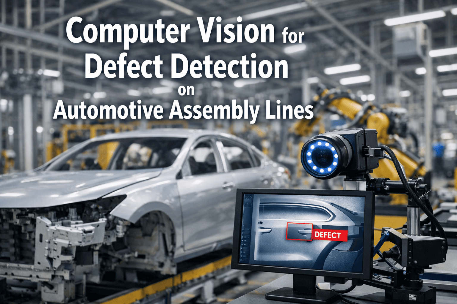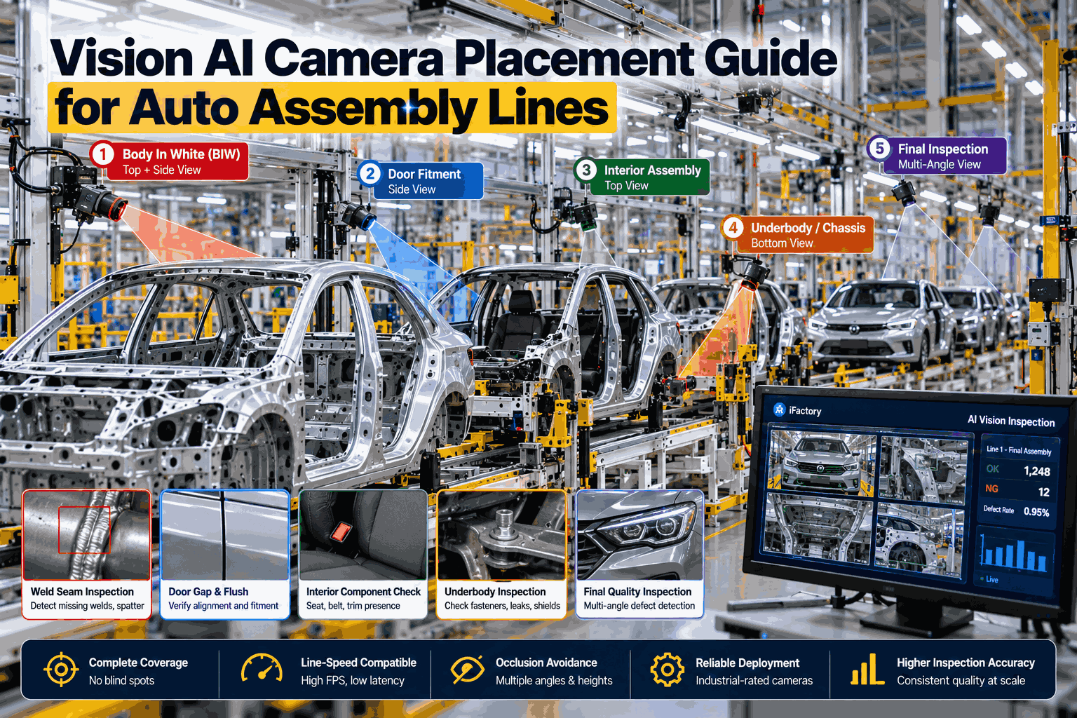
Most vision AI projects on an auto assembly line are won or lost before a model is trained — at the moment someone decides where the cameras go. A camera that is too far away cannot resolve the defect, one with too long an exposure smears it across the frame, and one behind a robot arm never sees it at all. This guide sets out how to place cameras for coverage, line-speed compatibility and occlusion avoidance, with the arithmetic behind each choice, so a deployment is reliable on day one and still reliable after the next model change. To have your own stations assessed, book a line survey.
Put the Camera in the Right Place and the AI Has an Easy Job
Three questions decide every position on the line: can the camera resolve the smallest defect, can it freeze the vehicle at line speed, and can it see the feature at the moment it is triggered. iFactory engineers answer all three for each station before any hardware is ordered — then deliver cameras, lighting and an NVIDIA AI server as one working system.
- Coverage sized to the defect, not to the camera on the shelf
- Exposure and trigger matched to conveyor speed
- Occlusion mapped against robots, carriers and operators
Why Placement Decides the Project
A deep-learning model can learn almost any defect it can see clearly, and almost none it cannot. When an inspection station underperforms, the cause is far more often optical than algorithmic: too few pixels on the feature, motion blur, glare off a painted panel, or a view that is blocked for part of the cycle. Retraining does not fix any of those. Moving the camera does. If a station on your line is producing false rejects today, our vision engineers can review its images with you.
Coverage
Every feature that must be judged falls inside a field of view, with enough pixels across it for the decision — and with overlap between neighbouring views so nothing sits on a seam.
Line-speed compatibility
The vehicle keeps moving. Exposure, lighting power and trigger timing are set so the image is sharp at conveyor speed and taken at the same body position every time.
Occlusion avoidance
Robots, carriers, hoses, open closures and people all pass between lens and part. Positions and triggers are chosen so the view is clear at the instant of capture.
Step One: Size the Field of View to the Defect
Start with the smallest thing the station must detect and work outwards. Imaging practice calls for at least two pixels across a feature to find it at all, and three to four for a dependable result. That fixes the millimetres each pixel may cover, and the camera's pixel count then fixes how wide a view it can take. Pick the camera after this sum, never before it. For a worked version on your own defect list, book a sizing session.
Pixel size on the part
Smallest feature ÷ pixels across it. A 1.0 mm clip judged with 4 pixels needs 0.25 mm per pixel.
Widest field of view
Pixel size × sensor pixels. At 0.25 mm per pixel, a 2,448-pixel sensor covers about 612 mm.
Working distance
Focal length × field of view ÷ sensor width. A 16 mm lens on an 8.45 mm sensor sees 612 mm at roughly 1.16 m.
Worked at 4 pixels per feature and one pixel of permitted blur; 5 MP taken as 2,448 pixels wide and 12 MP as 4,096. Use these as a starting point and confirm on real parts.
The last row explains why fine paint and surface defects are rarely inspected with general-purpose cameras on a moving line. At 0.2 mm, each camera covers barely 200 mm, which is why dedicated tunnels use many cameras or robot-carried deflectometry sensors with published resolutions near 185 microns.
Step Two: Freeze the Vehicle at Line Speed
A continuously moving final-assembly line is slower than it looks — about 0.11 to 0.13 metres per second at a takt of 46 to 60 seconds — but slow is not still. During the exposure the vehicle travels, and if it travels more than about one pixel the edge the model needs is gone. The longest usable exposure is simply the pixel size on the part divided by line speed, which is the right-hand column above. Blur of half a pixel to two pixels may be invisible to the eye and still degrade a measurement. Our application team can check exposure and lighting power for your conveyor speeds.
Short exposure, strong light
Exposures of a millisecond or less need far more light than the plant ceiling provides. Strobed LED lighting synchronised to the camera delivers it without heat or glare for operators.
Global shutter only
A rolling shutter reads the sensor line by line, so a moving body is skewed. Every pixel of a global-shutter sensor is exposed at the same instant.
Trigger on position, not time
A conveyor encoder or carrier-position signal fires the camera at the same point on every body. Timed triggers drift whenever the line slows, stops or restarts.
Let the line do the scanning
One fixed camera can take several frames as the vehicle passes. Five frames stepped along a body side replace five cameras — spend the saving on angles the first camera cannot see.
Get a Camera Plan for One Station Before You Buy Anything
Send drawings and a short video of the station. We return camera positions, lenses, lighting and trigger points with the resolution and exposure sums shown — then prove them on your line in a six-week pilot.
Step Three: Six Placement Patterns That Avoid Occlusion
Occlusion on an assembly line is rarely random. The robot is in the way at the same point of every cycle; the carrier arm hides the same patch of sill; the operator stands in the same place. That predictability is what makes it solvable. These six patterns cover most stations, and most stations need two of them combined. To see which fit your layout, book a layout review.
Portal in a clear zone
An arch of cameras in a transfer or buffer section with no robots and no operators. The vehicle passes through and the line does the scanning. Best for exterior, closures and full-body checks.
Opposed pair
Two cameras facing each other across the line, so a feature hidden by a carrier arm or an open door out of one side is seen by the other. Stagger them so neither lights the other's lens.
High-low pair
One camera overhead and one at a low angle for recessed features — engine bay, wheel arch, door aperture. The two views also let the AI separate a real defect and a shadow.
Clear-signal trigger
The camera stays where it is and waits. It fires only when the PLC reports the robot retracted or the light curtain clear, capturing in the gap the process already contains.
Eye-in-hand
A camera on the robot or a cobot goes where a fixed mount cannot: interiors, under the dash, inside the trunk. Slower per view, so keep it for features nothing else reaches.
Upward view
Cameras below the line for underbody fasteners, shields and routing. They need sealed housings, air purge across the window and a cleaning task in the maintenance plan.
Map occlusion before mounting anything. Take the station's cycle chart, mark when each robot axis, carrier and operator is inside each candidate view, and place the trigger where the chart is empty. iFactory does this on a 3D model of the cell where one exists, and on timed video where it does not.
Where Cameras Go, Shop by Shop
The physics is the same everywhere on the line; the hazards are not. Weld spatter, paint overspray and operator traffic each change what a workable position looks like. The grid below gives a starting pattern for each area and the environmental problem to design around.
Lighting sets the camera angle
Matte and textured parts
Plastics, fabric and sealer take diffuse light well. Mount the camera square to the surface, with ring or bar lights close to the lens axis.
Edges, embossing and scratches
Low-angle light makes raised and recessed detail stand out while the flat surface stays dark. The camera sits square on; the light sits almost parallel to the part.
Painted and chromed surfaces
Point a light at a glossy panel and the camera sees the lamp. Use large diffuse sources or striped patterns, polarisers where needed, and angle the camera off the mirror direction.
How iFactory Keeps a Placement Working
A position that is right at commissioning can be wrong six months later: a lens fogs, a bracket is knocked, a new model variant sits 40 mm lower on the carrier. iFactory treats the image itself as a monitored signal, so placement problems are caught as they begin instead of showing up as a week of false rejects. Ask our support engineers how this runs on existing cameras.
- Image-health checks on every frame. Brightness, focus and position of fixed reference points are tracked, so contamination, drift and misalignment raise an alert with the camera named.
- Variant-aware settings. Exposure, lighting and regions of interest follow the build record, so a black SUV and a white hatchback are each imaged correctly.
- Inference at the line. Models run on an NVIDIA AI server in the plant, returning a result inside the station cycle with images kept on site.
- Results where they are used. Pass, fail and defect location go to the PLC, the andon and the unit's quality record.
Commissioning Checklist: Prove the Placement Before Go-Live
A placement is proven with parts, not drawings. Work through these eight checks at each station before the result is allowed to stop a vehicle. For a copy tailored to your stations, book a commissioning call.
Resolution on a real part
Image a scale or target at the part surface and confirm the pixel size matches the sum.
Sharpness at full line speed
Capture at maximum conveyor speed, not at a standstill, and inspect edges for blur.
Depth of field across variants
Check the tallest and lowest models stay in focus without refocusing.
Clear view on every cycle
Record a full shift and confirm no frame is blocked by robot, carrier or person.
Every colour and trim
Run the darkest, lightest and most reflective variants and confirm exposure holds.
Known-bad parts
Pass seeded defects through and count how many are caught, by defect type.
Repeatability
Send the same body through several times; the result and the measured position should not change.
Mounting and cleaning
Confirm the bracket is off vibrating structure, the housing is sealed, and cleaning is in the PM plan.
Delivered as a Turnkey AI System — Hardware and Software Together
iFactory ships as a complete bundle: a pre-configured NVIDIA AI server, racked and ready, with vision models and the inspection software pre-loaded, plus the cameras, lenses and lighting the station plan calls for. Rack it, plug in power and Ethernet, and the AI is live. Our team handles brackets and cabling, network setup, PLC and SCADA integration, operator training and 24×7 remote monitoring — so your controls engineers are not left tuning exposure times at midnight. For a scoped proposal, speak with our deployment team.
Ship, network and data
Station survey and camera plan signed off. Server, cameras and lighting delivered and mounted. Triggers wired to the PLC and first images collected across variants.
Model training and pilot
Models trained on your own parts and defects. The station runs in shadow mode while positions, exposure and lighting are tuned against the commissioning checklist.
Go-live and training
Results switched through to the PLC and quality record. Operators, quality and maintenance trained, with camera cleaning and checks added to the PM plan.
Frequently Asked Questions
How many cameras does an auto assembly inspection station need?
It follows from the sums, not from a standard number. Divide the area to be covered by the field of view each camera can take at the pixel size the defect requires, then add views for angles the first cameras cannot see. A connector check may need two or three cameras; a full exterior portal can need a dozen or more; fine paint inspection needs a dedicated tunnel.
What resolution camera should we use?
Work back from the smallest defect. Allow three to four pixels across it, which gives the pixel size on the part, and multiply by the width of view you want. A 1 mm feature across a 600 mm view needs about 2,400 pixels, so a 5 MP camera fits. More megapixels than the sum requires add cost, data and processing time without adding detection.
Do we have to stop the line to take a sharp image?
Usually not. At typical conveyor speeds of around 0.11 metres per second, exposures of one to four milliseconds with strobed lighting freeze most assembly features. Only the finest surface defects call for a stop station or a purpose-built tunnel, because their pixel size leaves an exposure budget under half a millisecond.
How do we deal with robots and operators blocking the view?
Treat occlusion as a timing problem first. Most blockages are at the same point of every cycle, so triggering on the robot's clear signal or between operator tasks often solves it without moving anything. Where it does not, use an opposed or high-low pair, or move the camera to a clear zone downstream.
Can vision AI compensate for a poor camera position?
Only slightly. A model can tolerate some variation in lighting and pose, but it cannot recover detail that was never captured — too few pixels, motion blur or a hidden feature. Fixing the optics is nearly always quicker and more durable than collecting more training images for a bad view.
Can iFactory use cameras we already have installed?
Often, yes. Existing industrial cameras with standard interfaces can be connected to the iFactory server, and the survey will show whether their position, lens and lighting meet the sums for the defects you care about. Where they fall short, we specify the change — sometimes a lens or a light, not a new camera.
How long does a deployment take?
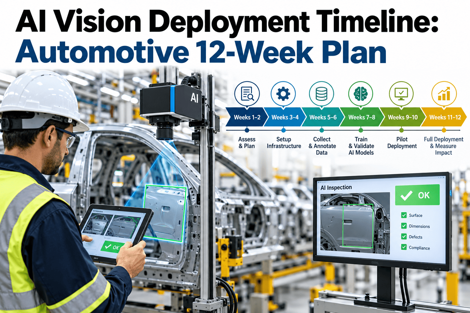
A typical station or group of stations is live in 6–12 weeks, including the survey, mounting, model training on your parts and commissioning. You provide station access, drawings, a PLC contact and sample good and defective parts. To scope your line, book a scoping call.
Cameras Placed Right, AI Running, in 12 Weeks
One turnkey system — NVIDIA AI server, cameras, lighting, integration and training — designed around your stations and proven on your parts. Start with the station that generates the most rework and extend along the line.
- 1Are there 3–4 pixels across the smallest defect?
- 2Does the vehicle move less than one pixel during exposure?
- 3Is the view clear at the instant of the trigger?