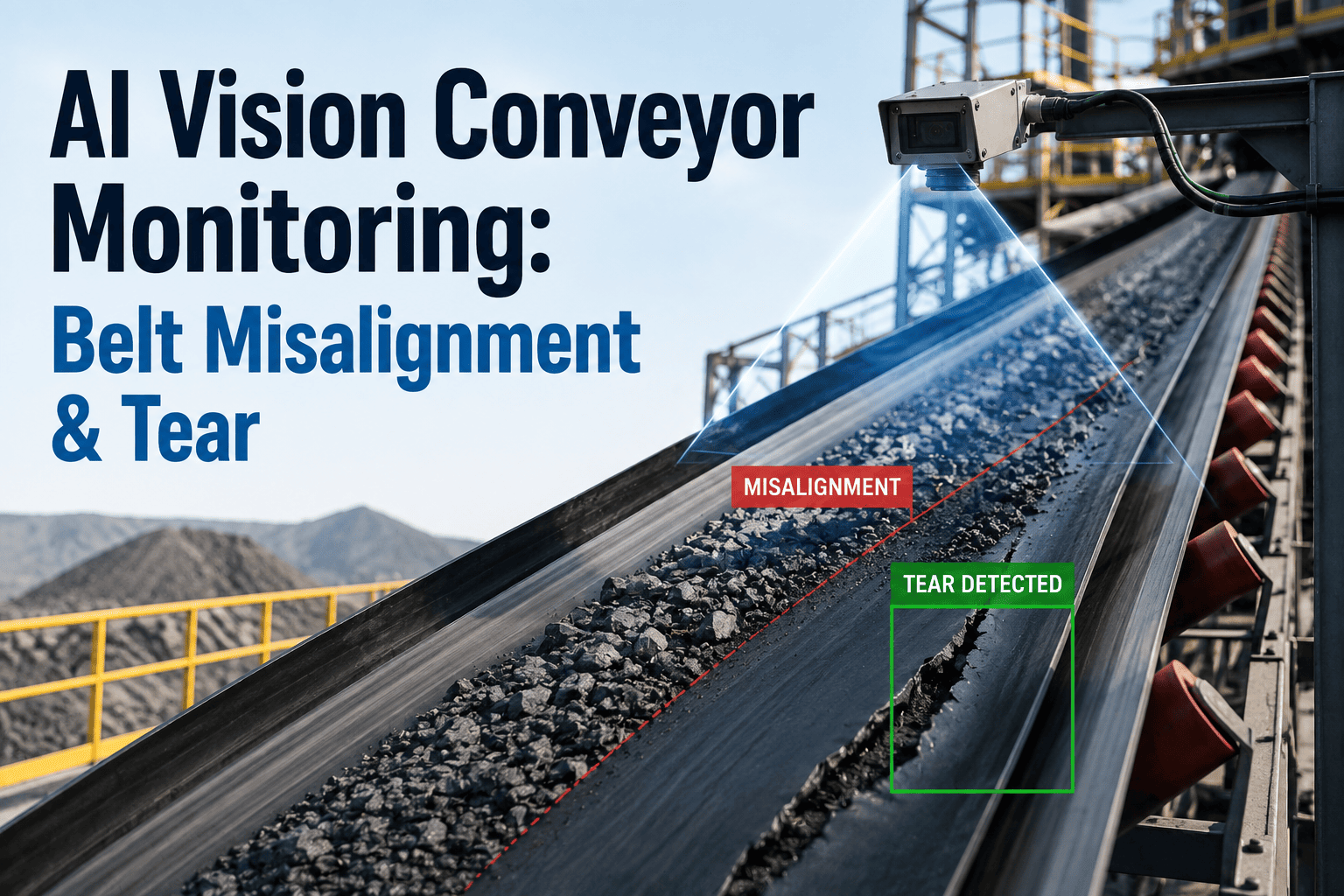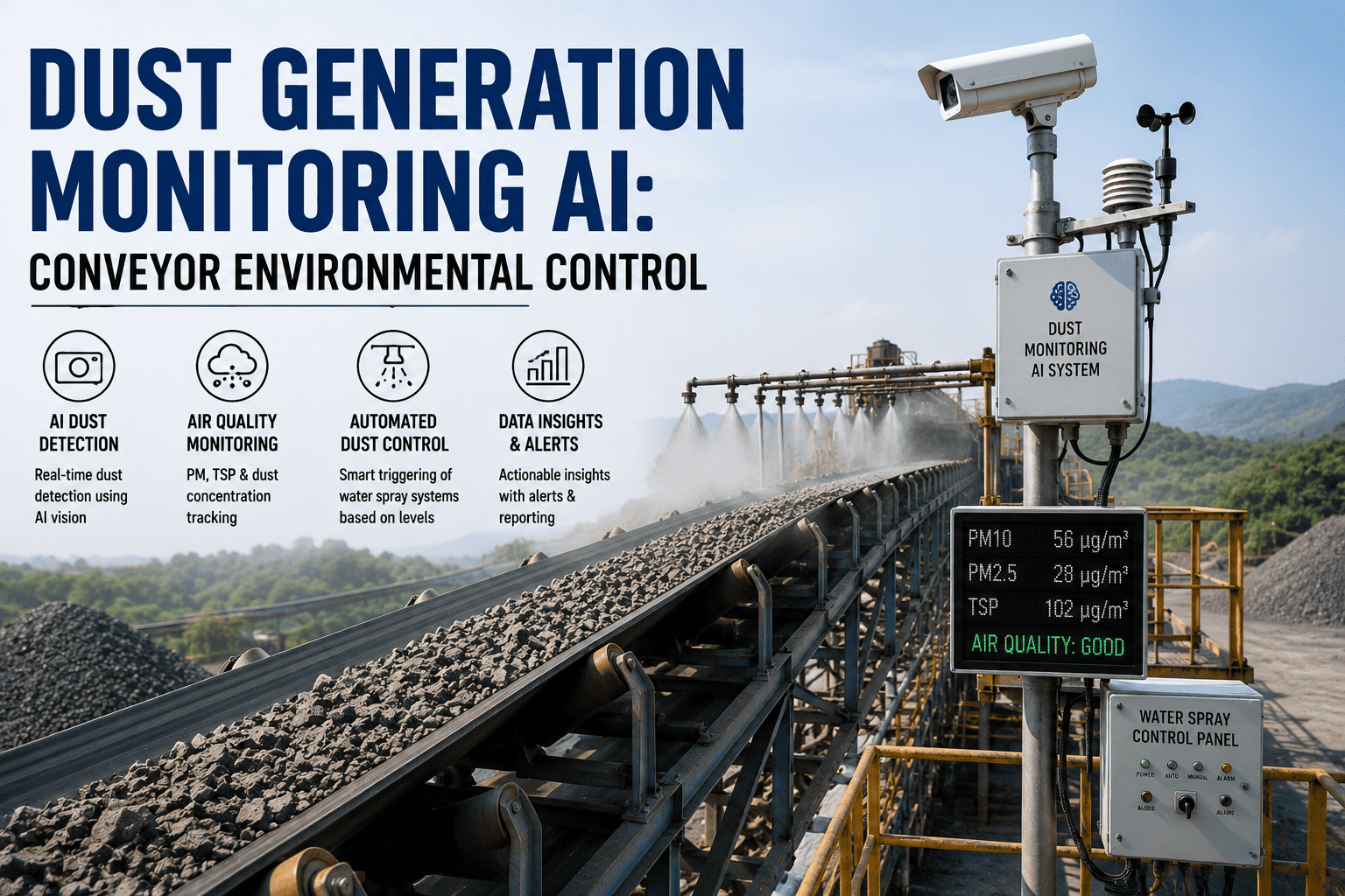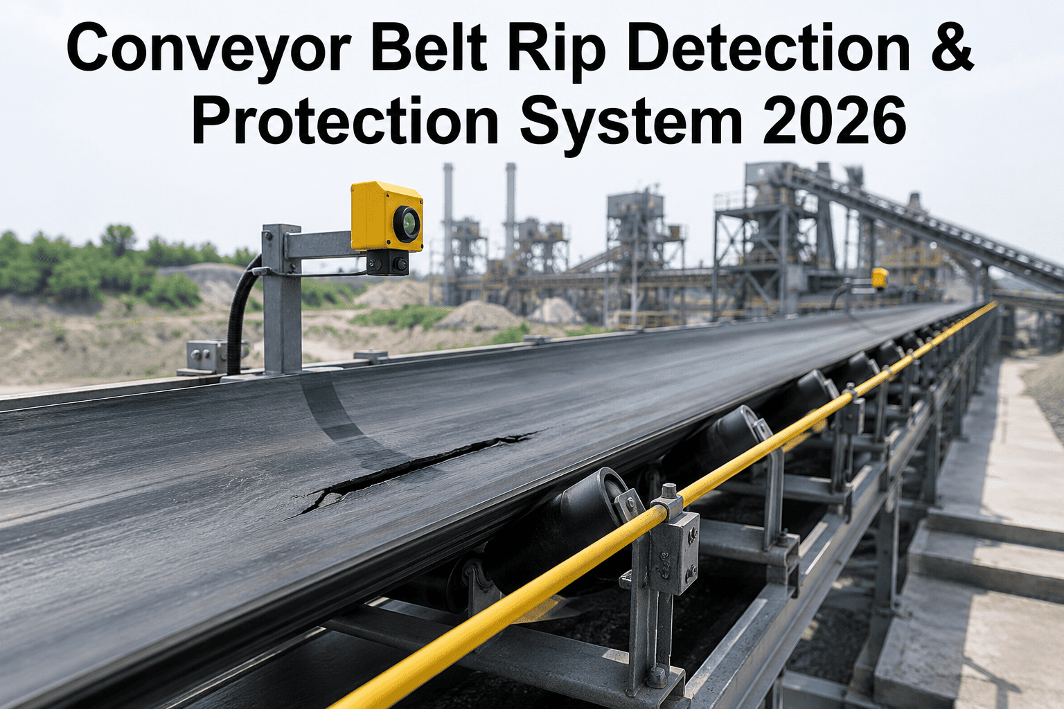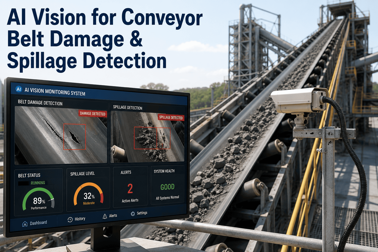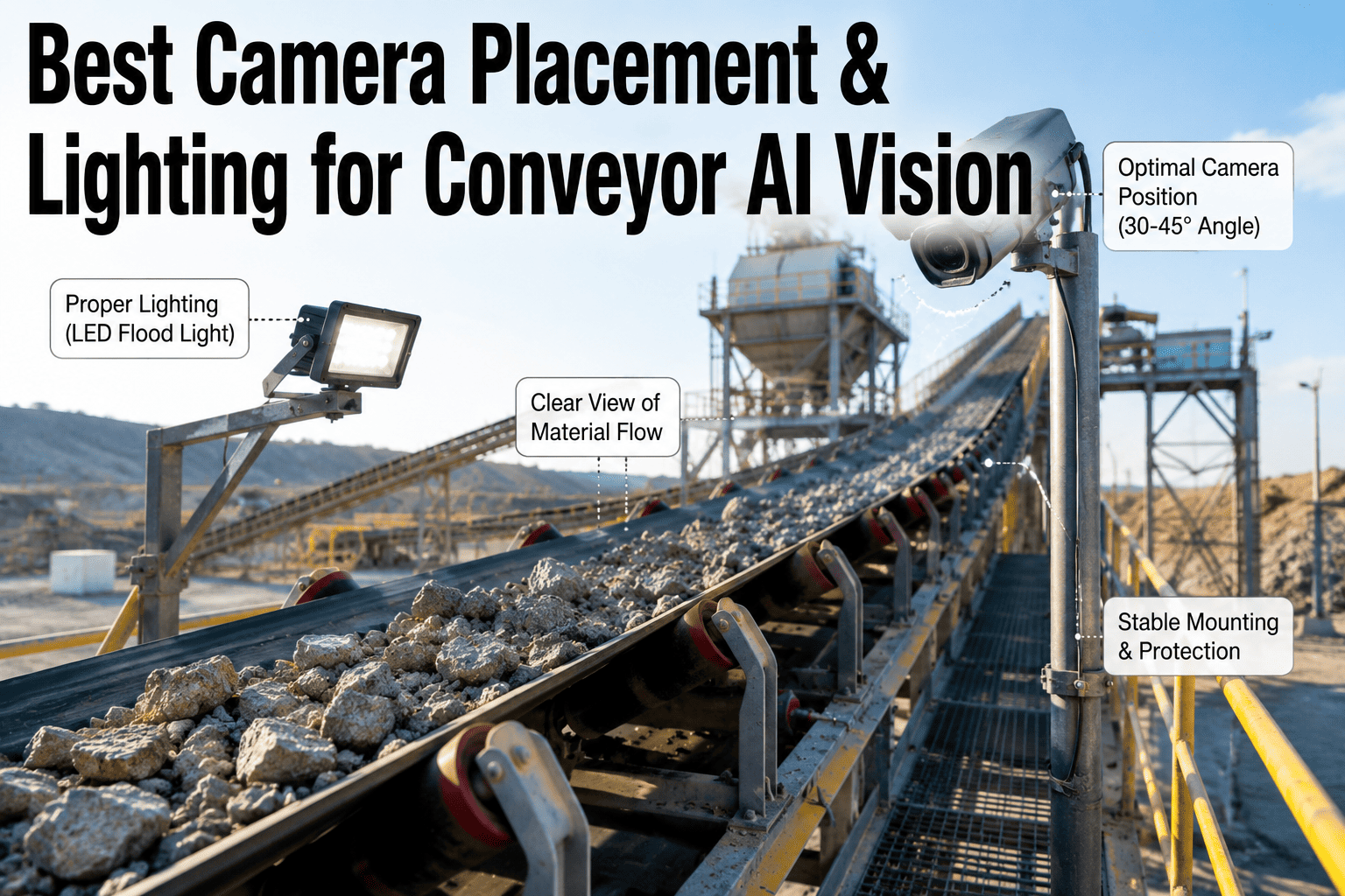
Ask why a conveyor AI vision system is missing blockages or flagging false alarms and the conversation almost always starts with the model — maybe it needs retraining, maybe the dataset was too small. In most deployments the real answer is sitting a few feet away from the screen: a camera mounted at the wrong angle, a lighting rig that leaves half the belt in shadow, or a housing that was never rated for the dust a cement conveyor throws off every shift. Lighting alone has been shown to swing detection accuracy by 15 to 30 percent between morning and afternoon on the same line when it isn't controlled for, which means the placement and illumination decisions made before a single frame is ever analyzed matter more than almost anything that happens inside the AI model itself — book a demo to see how iFactory scopes camera and lighting layout before a single unit goes on your conveyor.
The Camera Doesn't Fail Because the AI Is Wrong. It Fails Because the Light Was Wrong First
A conveyor AI vision system is only as reliable as the image it starts with. Get the mounting angle, coverage zone, and illumination geometry right and the model has a clean, consistent frame to work with every time. Get any one of them wrong and the system spends its life fighting shadows, glare, and dust instead of watching the belt.
Lighting Is Pre-Processing That Happens Before the Camera Ever Fires
It is tempting to treat lighting as a minor accessory to the camera, something to sort out after the hardware is mounted. In practice, lighting functions as parallel pre-processing on every single pixel the camera captures — it either hands the AI model a clean, high-contrast frame or it hands the model a frame the model then has to computationally fight to correct. Physically conditioning the image through correct lighting geometry is dramatically more efficient than trying to fix poor contrast after the fact, and it's also the difference between a detection model that works consistently and one that only works on the sunny days it happened to be trained on.
Three Conveyor Zones Need Fundamentally Different Camera Coverage
A conveyor is not one visual scene, it is several distinct zones stitched together, and each one presents a different inspection target, a different working distance, and a different set of lighting obstacles. Treating the whole belt as a single camera problem is the fastest way to end up with a system that covers none of these zones particularly well.
Chute Discharge & Transfer Points
Where blockages, carryback, and spillage originate. Cameras need a downward or angled view into the chute opening with a wide enough field of view to catch material buildup before it becomes a full blockage, and this zone is almost always the dustiest on the entire conveyor line.
Belt Load Zone
The straight run where overload conditions, tramp material, and foreign objects are most visible against the moving material stream. This zone benefits from a perpendicular, elevated mounting position that captures the belt's full width in a single consistent frame.
Drive, Return & Idler Points
Where mistracking, belt damage, and idler wear show up first. These points need closer working distances and tighter fields of view than the open belt run, since the defects being watched for are smaller and more localized.
Coverage Angle and Working Distance Are Not One-Size-Fits-All
Once the zone is identified, the mounting geometry follows from what the camera is actually being asked to see. A wide-area overload check and a small localized idler-wear check call for almost opposite setups.
| Zone | Recommended Angle | Working Distance | Primary Risk If Wrong |
|---|---|---|---|
| Chute discharge | 30-45° downward into chute | Close, 0.5-1.5m | Blind spot at blockage origin |
| Belt load zone | Perpendicular, elevated overhead | Medium, 1.5-3m | Partial width coverage, edge misses |
| Transfer point impact area | Angled, avoiding spillage cone | Close, 0.5-1m | Lens fouling from spillage |
| Drive/return/idler | Near-perpendicular, tight FOV | Very close, 0.3-1m | Missed small-scale defects |
Every one of these positions needs to be locked to a drawing before installation, not adjusted by feel on the day the camera goes up. A position that drifts even a few millimeters from its specified location changes the field of view enough to shift the AI model's effective coverage, which is why leading installation practice ties camera X-Y-Z position to a tolerance as tight as two millimeters against the original layout drawing, with reference marks photographed so any future service event restores the exact position rather than approximating it.
Four Lighting Techniques, Each Built for a Different Kind of Detection
Machine vision lighting is not a single floodlight problem, it is a geometry problem, and the technique needs to match what the AI model is actually trying to see. Choosing the wrong geometry for the detection target is one of the most common and most fixable causes of inconsistent conveyor AI vision performance.
Diffuse / Bright Field Lighting
Multi-directional light from a dome or ring arrangement eliminates shadows and hotspots across a wide, uneven surface like a loaded belt. This is the default choice for general material flow and overload monitoring where uniform coverage across the full belt width matters more than highlighting fine surface detail.
Dark Field Lighting
Light positioned at a low grazing angle, typically under 45 degrees, skims across the surface so raised or textured features scatter light toward the camera while flat, smooth areas stay dark. This is the technique that reveals belt surface damage, cracks, and embedded foreign material that flat, direct lighting would miss entirely.
Backlighting
Placing the light source behind the material creates a high-contrast silhouette, ideal for foreign object detection where the outline and shape of an object against the material stream matters more than surface texture. The tradeoff is that backlighting conceals surface detail entirely, so it is the wrong choice anywhere surface condition is the actual inspection target.
Strobe Lighting
A short, intense burst synchronized precisely with the camera's exposure freezes motion on a fast-moving belt without needing to slow the conveyor down, and industrial strobe systems can be overdriven several times their normal brightness for these brief bursts, sharply reducing the motion blur that a continuous light source can't fully eliminate at belt speed.
A Cement Conveyor Is One of the Harshest Environments a Camera Will Ever Operate In
Dust, vibration, humidity swings, and temperature extremes are not occasional conditions on a cement conveyor line, they are the baseline operating environment every day of the year. A camera and lighting system specified for a clean indoor inspection cell will degrade quickly here, which is why harsh-environment hardware needs to be the starting assumption for conveyor deployments, not an upgrade added after the first failure.
Sealed, Rated Housings
IP65 or IP67-rated enclosures are the practical minimum anywhere dust, moisture, or washdown procedures are present, protecting both the camera and the light source from the airborne clinker and raw meal dust that would otherwise coat optics within hours.
Air Purge & Wiper Systems
A sealed housing keeps dust out, but lens fouling from ambient airborne particulate still needs active management. Air purge systems maintain a positive pressure across the lens surface, and wiper options clear material that does settle, both critical for chute and transfer point cameras.
Vibration Isolation
Conveyor structures transmit vibration continuously through drives, idlers, and structural framing. Mounting a camera directly to a vibrating frame introduces blur that degrades detection accuracy long before any dust or lighting issue does, so isolated mounts on separate, stable foundations are essential wherever fine-detail detection is required.
Temperature extremes deserve equal attention. Both the camera sensor and the lighting components have a rated operating range, and a cement plant's ambient conditions — combined with heat radiating off nearby process equipment — can push past that range in ways an indoor factory installation never has to consider. Specifying hardware rated for the actual environment, not the environment on the datasheet's default assumption, is what keeps a system performing consistently through a full year of seasonal swings rather than degrading every summer.
Cable and connectivity infrastructure needs the same environmental scrutiny as the camera itself, since a ruggedized housing does little good if the power and network cabling running to it is exposed to the same dust and moisture the housing was designed to resist. Conduit routing, sealed connectors, and strain relief at every junction point are easy to overlook during planning and expensive to retrofit once a conveyor is back in continuous operation, which is why they belong in the same site survey that determines camera position and lighting geometry rather than being treated as a downstream electrical detail.
Built for Dust, Vibration, and Heat From Day One
iFactory's ruggedized camera housings are rated for the dust, humidity, vibration, and temperature extremes of a working cement conveyor line, with air purge and wiper options for the dustiest transfer points.
Five Camera and Lighting Errors That Look Fine on Installation Day
The hardest placement and lighting mistakes to catch are the ones that pass a same-day commissioning check and only show their cost weeks or months later, once conditions shift away from whatever they happened to be during setup.
Why a Site Survey Should Happen Before Any Camera Is Ordered
The single most common shortcut that leads to underperforming conveyor AI vision systems is ordering hardware before the site has actually been surveyed. A camera and lighting spec that works well on a datasheet or on a similar-looking line at a different plant can still be the wrong choice for a specific chute geometry, a specific ambient lighting pattern, or a specific dust load, because no two conveyor installations share exactly the same combination of structure, access, and environmental conditions. A proper survey walks each zone of the conveyor, documents existing structure available for mounting, measures ambient light levels and how they shift across a working day, and identifies where vibration, dust, and moisture are most severe, before any camera model or lighting fixture gets specified.
That survey output becomes the layout drawing every subsequent installation decision gets measured against — camera position, mounting angle, working distance, and lighting geometry per zone, all tied to specific, documented coordinates rather than judgment calls made on installation day. Skipping this step doesn't just risk a suboptimal first installation, it risks a system that needs to be re-engineered zone by zone after go-live, once gaps in coverage or lighting inconsistency show up in the model's real-world performance instead of in a planning document where they would have been far cheaper to catch. iFactory's deployment team conducts exactly this kind of survey before any camera or lighting fixture is ordered, so the layout drawing reflects your actual conveyor structure and conditions rather than a generic template. Contact our support team to scope a site survey for your conveyor lines.
Getting the Layout Right Once Isn't the Same as Keeping It Right
A camera and lighting system that passes commissioning with strong detection accuracy on day one is not automatically the same system six months later. Conveyor structures shift slightly under continuous operation, lighting fixtures degrade in output over their service life, and seasonal changes in ambient light or temperature can expose gaps that simply weren't visible during a single installation-week test window. Plants that treat camera and lighting design as a one-time project rather than an ongoing discipline tend to be the ones surprised months later when detection accuracy has quietly drifted without any single dramatic failure to point to.
Building a verification routine around the same documented layout used during installation — checking camera position against reference marks, confirming lighting output against baseline readings, and reviewing detection performance across different times of day and seasons — closes that gap. This is the same logic that applies to any other precision equipment on a conveyor line: the initial specification matters, but the maintenance discipline that keeps that specification holding true over years of operation is what actually determines whether the investment keeps paying off.
Questions Plant Teams Ask Before Installing Conveyor AI Vision Cameras
Get Your Camera and Lighting Layout Right Before Installation Day
iFactory surveys your conveyor's zones, specifies mounting angle and working distance per point, and matches lighting geometry to what each camera actually needs to detect — before hardware goes up.